Device for controlling or regulating auxiliary brake torque in a motor vehicle

a technology of auxiliary brake and motor vehicle, which is applied in the direction of braking system, process and machine control, instruments, etc., can solve the problems of transmission components being exposed to stresses in excess of their maximum torque capacity, high risk of combined brake force, and high cos

a technology of auxiliary brake and motor vehicle, which is applied in the direction of braking system, process and machine control, instruments, etc., can solve the problems of transmission components being exposed to stresses in excess of their maximum torque capacity, high risk of combined brake force, and high cos

US20050052075A1Inactive Publication Date: 2005-03-10VOLVO LASTVAGNAR AB

Image

  • Device for controlling or regulating auxiliary brake torque in a motor vehicle
  • Device for controlling or regulating auxiliary brake torque in a motor vehicle
  • Device for controlling or regulating auxiliary brake torque in a motor vehicle

Examples


Embodiment Construction

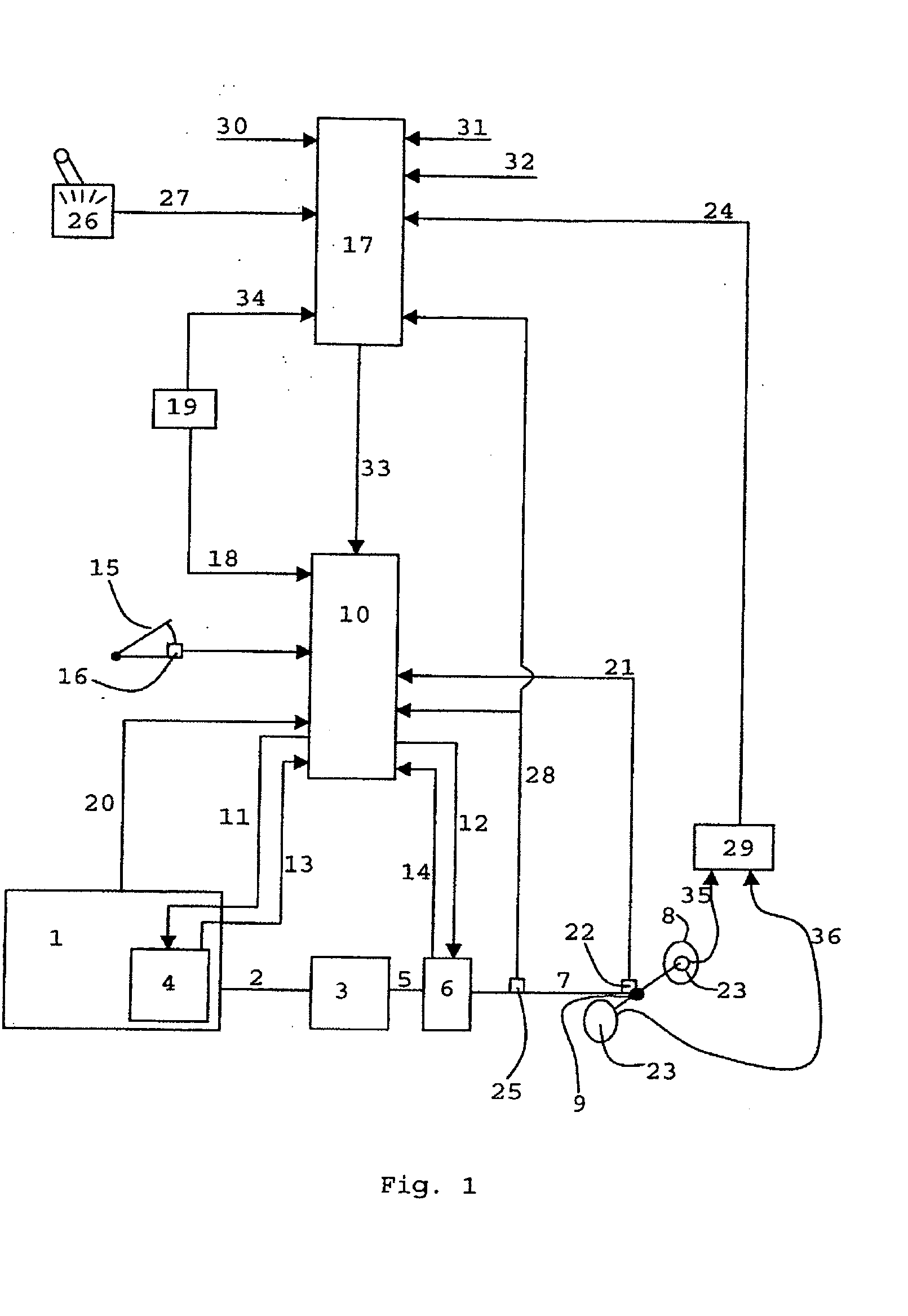
[0026]FIG. 1 shows a diagrammatic representation of a system configured according to the present invention suitable for controlling and / or regulating an auxiliary brake torque in a vehicle. An engine 1 is connected by an output shaft 2 to a transmission 3 which is the main transmission of the vehicle, and which usually offers the possibility of driving the vehicle both forward and in reverse utilizing many different gear ratios between the engine 1 and drive wheels 8. The transmission 3 can be equipped with auxiliary transmissions (for example a splitter transmission or range-change transmission) in order to obtain more drive gears. In the engine 1, a primary auxiliary brake 4 is disposed. It should be noted that the primary auxiliary brakes can also be disposed between the engine 1 and the transmission 3, or in the transmission on its input shaft. An auxiliary brake of, for example, the compression brake-type is disposed in the engine 1. A retarder is usually disposed on the input ...


PUM


Abstract

Method and arrangement for controlling or regulating total auxiliary brake torque in a motor vehicle. The device includes at least one first auxiliary brake (4) of a first type and at least one second auxiliary brake (4, 6) of a second type that is different from the first type. The second auxiliary brake (4, 6) can take the form of a retarder (4, 6). A control system (10, 17) is provided for controlling or regulating the auxiliary brake. Information is stored in the control system regarding characteristics of the respective auxiliary brake (4, 6) and at least one predefined limit value for maximally permitted auxiliary brake torque. The control system (10, 17) is designed such that, if the limit value is exceeded or if a request is made for the brake force from the auxiliary brakes (4, 6) to be moderated, then this is done by turning down or moderating, in the first place, the brake torque of the retarder (6).

Description

CROSS-REFERENCE TO RELATED APPLICATIONS [0001] The present application is a continuation patent application of International Application No. PCT / SE02 / 02460 filed 30 Dec. 2002 which was published in English pursuant to Article 21(2) of the Patent Cooperation Treaty, and which claims priority to both Swedish Application No. 0200222-8 filed 25 Jan. 2002. Said applications are expressly incorporated herein by reference in their entireties.TECHNICAL FIELD [0002] The present invention relates to a device for controlling and / or regulating the total auxiliary brake torque in a vehicle equipped with an engine, drive wheels and transmission components incorporated between the engine and the drive wheels. BACKGROUND ART [0003] It is known to fit auxiliary brakes on a vehicle that is equipped with an engine and drive wheels, with transmission components incorporated therebetween, and which components include a main transmission with which a driver of the vehicle can select different gears for f...

Claims


Application Information

Patent Timeline
10 Mar 2005
Publication
US20050052075A1
IPC
B60T10/02; B60T13/58; B60T13/66
CPC
B60T10/02; B60T13/585; Y10T477/679; Y10T477/644; B60T13/662
Inventors
SABELSTROM, MATS; WALLGREN, HANS