
Laminate panel for use in structrual components

a technology of structrual components and laminate panels, applied in the field of laminate panels, can solve the problems of difficult, or impossible, to obtain using water or solvent-based digital ink jet inks, and achieve the effects of easy and fast change, easy and fast change of advertising murals, and higher ink loadings

Inactive Publication Date: 2005-03-10
THE BOEING CO
View PDF26 Cites 39 Cited by
  • Summary
  • Abstract
  • Description
  • Claims
  • Application Information

AI Technical Summary

Benefits of technology

[0007] It is also an important advantage of the present invention that the laminate panel of each stowage bin door is constructed to form an integral, permanently attached portion of the bin door. Thus, the message or mural can be quickly and easily changed simply by removing one set of stowage bin doors and attaching a different set of stowage bin doors having a different advertising message or mural incorporated thereon. Furthermore, there is no need to use adhesives or any solvents to clean the surfaces of the bin doors before the advertising message or mural can be changed. This makes the changing of the advertising mural easier and more quickly accomplished than with some arrangements that incorporate the use of adhesives for securing the advertising materials to their support panels. In addition, incorporating the advertising material into the bin door provides a fireworthy colorfast, cleanable, and abrasive, stain and solvent resistant surface.

Problems solved by technology

In addition, UV curable inks can allow significantly higher ink loadings on the Tedlar® PVF, in some cases possibly in excess of 300%, which is difficult, or impossible, to obtain using water or solvent based digital ink jet inks.

Method used


Image

  • Laminate panel for use in structrual components
  • Laminate panel for use in structrual components
  • Laminate panel for use in structrual components

Examples


Embodiment Construction

[0013] The following description of the preferred embodiment(s) is merely exemplary in nature and is in no way intended to limit the invention, its application, or uses.

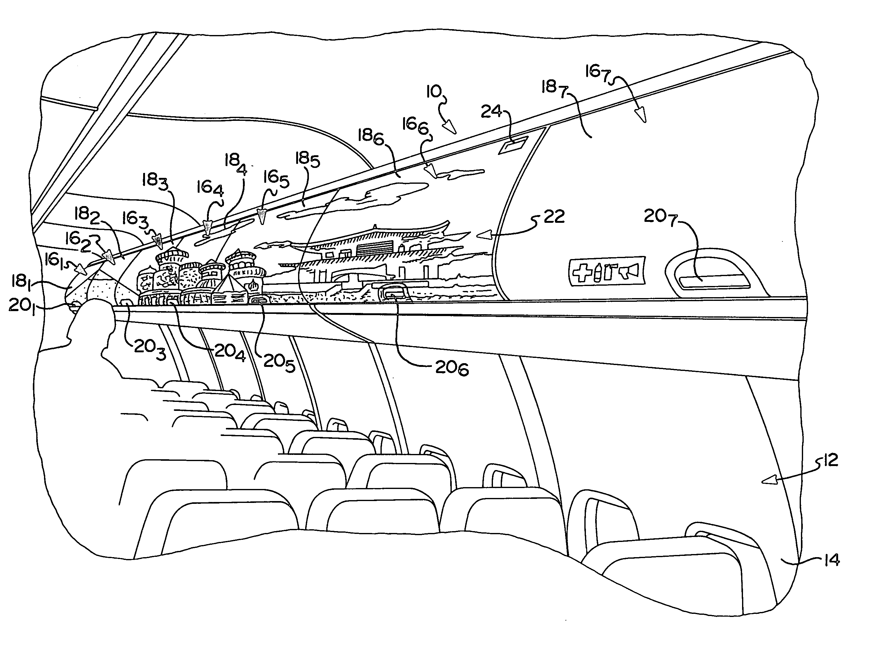
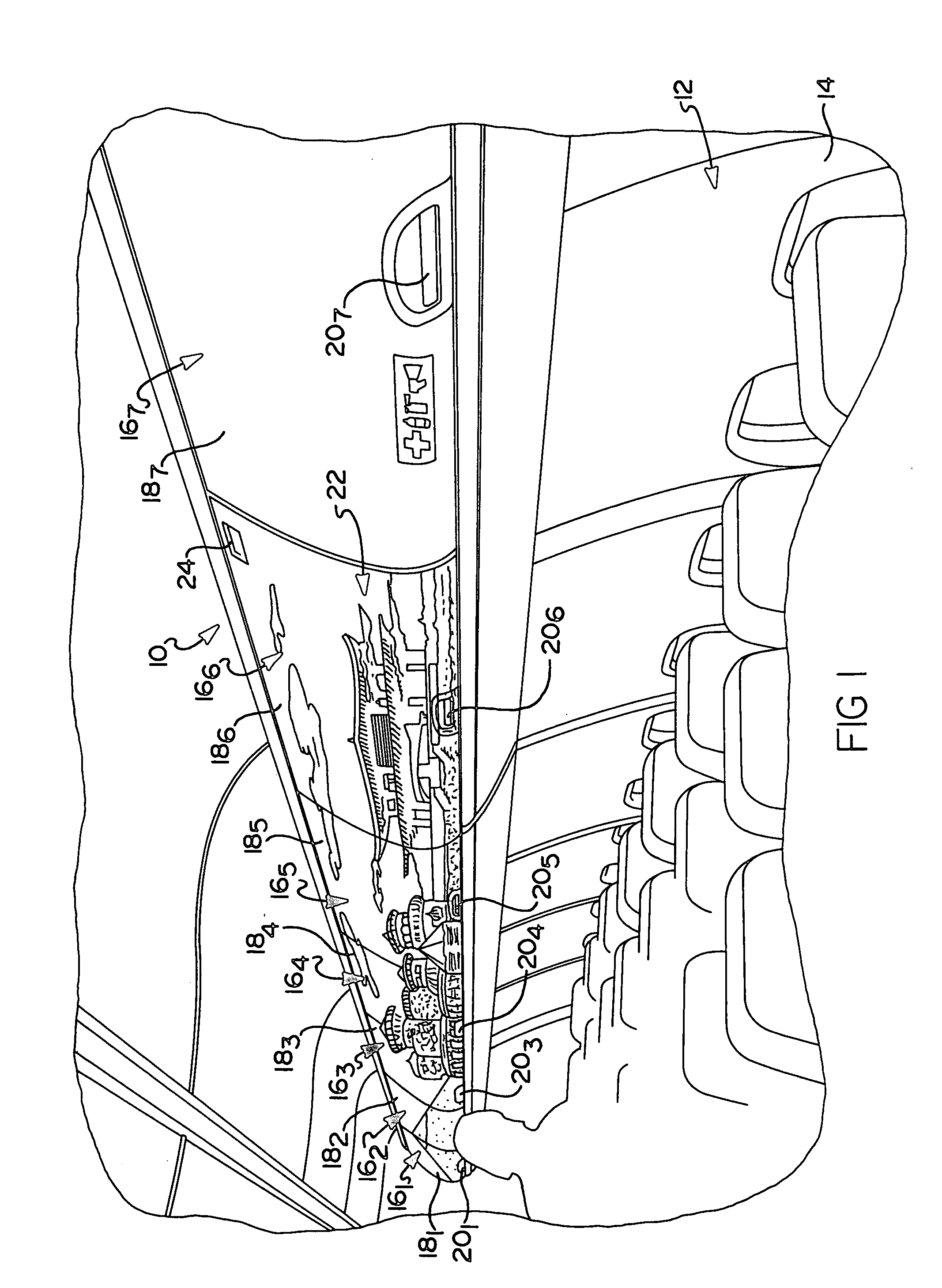
[0014] Referring to FIG. 1, there is shown an overhead stowage bin door system 10. The stowage bin door system 10 is disposed in a passenger cabin area 12 of a commercial aircraft 14. It will be appreciated that most typically, a commercial aircraft will include the stowage bin door system 10 on both the port and starboard sides of the passenger cabin 12. In larger commercial aircraft, such as a twin aisle aircraft, the stowage bin system 10 will also be present over the central area of the cabin (i.e., the area over the seats disposed between the two aisles).

[0015] The stowage bin system is comprised of a plurality of independent stowage bin doors 161-16n, which are laterally aligned to form a generally continuous overhead storage area. Each stowage bin 161-16n includes an associated bin door 181-18n which may be ...


PUM

PropertyMeasurementUnit
ultraviolet stableaaaaaaaaaa
color imageaaaaaaaaaa
adhesiveaaaaaaaaaa

Abstract

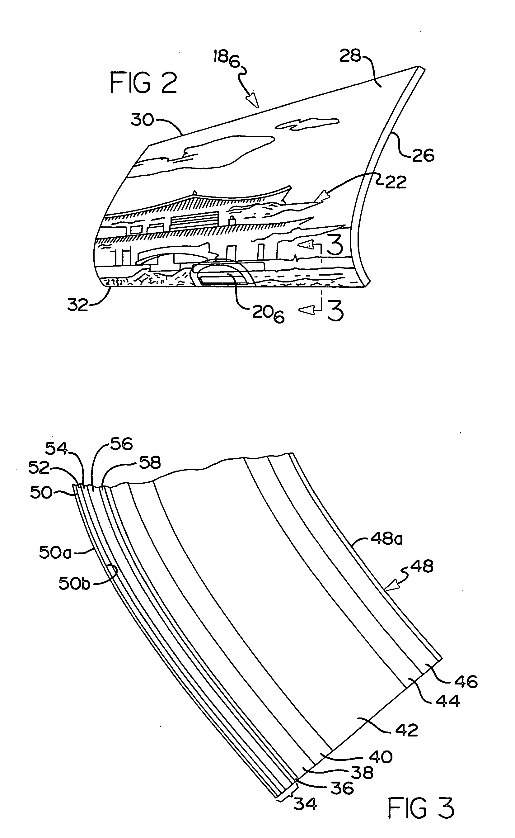
A laminate panel especially well suited to help form an overhead stowage bin door on an aircraft, wherein the door includes a portion of a high contrast color advertising mural or message integrally formed therewith. The door includes a honeycomb support layer on which at least one fiberglass pre-preg layer is formed. A polyvinyl fluoride (PVF) film is used as a substrate for the color mural or message. A ultraviolet (UV) curable ink is deposited directly on the PVF film via an ink jet printing process that produces a high color density, high color contrast image. The PVF film in one form is a Tedlar® PVF film. The ink is cured virtually immediately after it is deposited on the PVF film. An additional layer of PVF film is then secured to a side of the printed-on PVF film opposite to that on which the ink is deposited via a layer of embossing resin to form the laminate panel. The laminate panel is then secured via a suitable adhesive to the fiberglass pre-preg and honeycomb support layer in a subsequent manufacturing step. The stowage bin door and process of making same enable a portion of a high color density, high contrast image, advertising mural or message to be integrally formed with the door.

Description

FIELD OF THE INVENTION [0001] The present invention relates to laminate panels, and more particularly to a laminate panel that can be used to form an advertising system on panels such as stowage bin doors used in an aircraft. BACKGROUND OF THE INVENTION [0002] In a commercial aircraft, a plurality of laterally aligned overhead stowage bin doors are typically included along the port and starboard sides of the passenger cabin of the aircraft. Larger commercial aircraft may even have one or more rows of overhead stowage bin doors located along a central area of the passenger cabin between a pair of aisles within the passenger cabin. Each of the stowage bins includes a door which can be raised by a passenger or crew member. The stowage bin doors, when closed, are readily visually apparent to the passengers and crew members within the passenger cabin area of the aircraft. [0003] The stowage bin doors, when in their closed positions, form either relatively flat or only slightly curving su...

Claims


Application Information

Patent Timeline
Patent Type & Authority Applications(United States)
IPC IPC(8): B32B3/12B32B17/04B32B27/30B64D11/00G09F21/08
CPCB32B3/12B32B17/04G09F21/08B64D11/003B32B27/30B32B5/24B32B7/12B32B27/304B32B2262/101B32B2305/076B32B2307/41B32B2435/02
Inventor WILDE, JOHN C.FINNEGAN, JODY L. P.
Owner THE BOEING CO
Learn More