
Wireless communication system, and demodulation method and data rate control method therefor

Inactive Publication Date: 2005-03-10
HITACHI LTD
View PDF4 Cites 28 Cited by
  • Summary
  • Abstract
  • Description
  • Claims
  • Application Information

AI Technical Summary

Benefits of technology

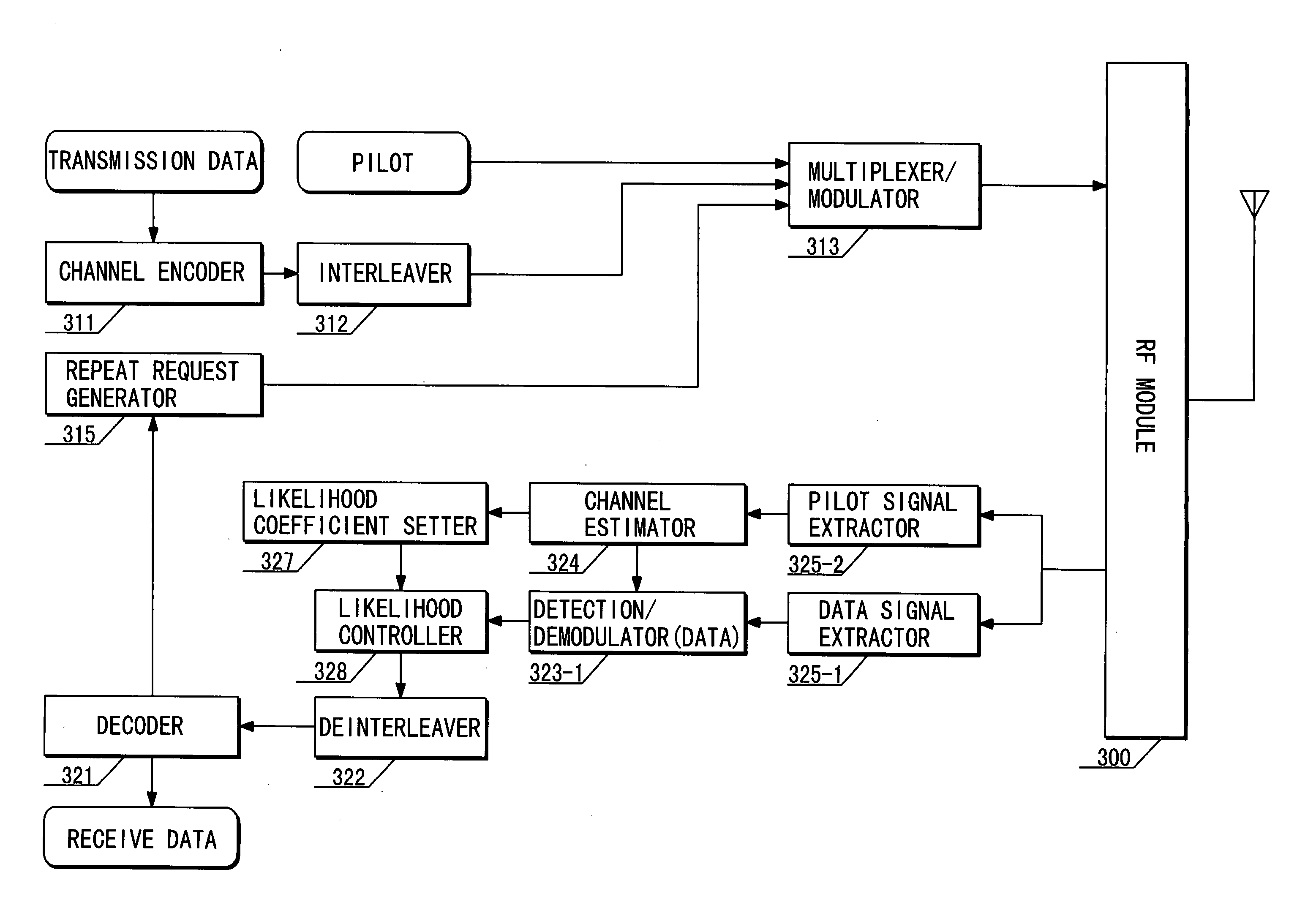
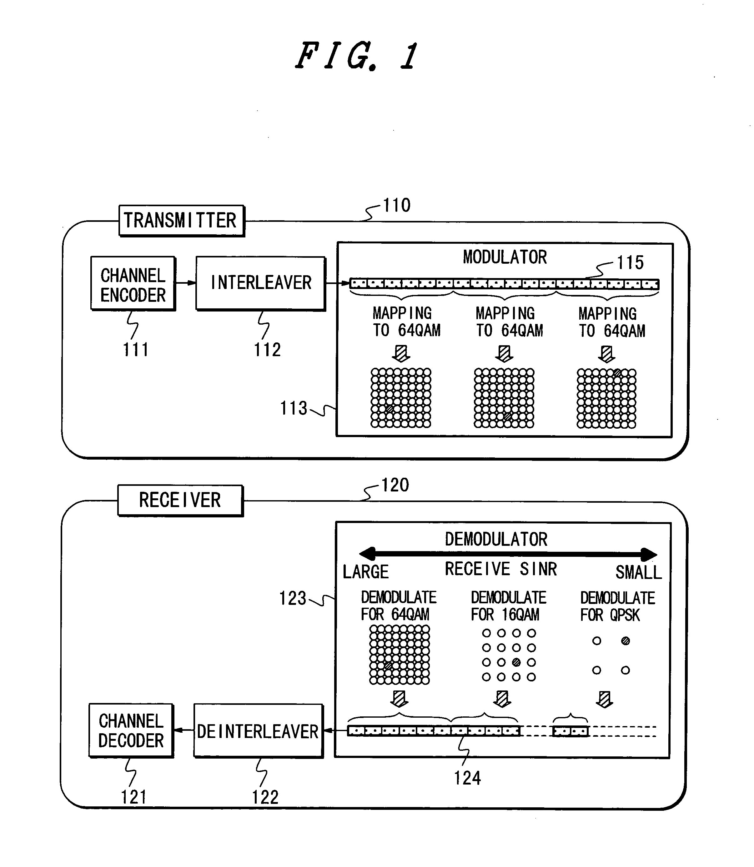
[0012] To achieve the above object, in a communication system according to a first aspect of the present invention, a transmitter and receiver share a maximum number of transmission bits per symbol as a parameter. The transmitter modulates an encoded and interleaved transmission signal in accordance with a modulation scheme which enables the transmission of one or more bits per symbol. When the number of bits per symbol which can be modulated by the modulation scheme is below the maximum number of transmission bits per symbol, the transmitter discards the remaining bits and modulates the next symbol. The receiver demodulates a received signal in accordance with a modulation scheme which enables the transmission of one or more bits per symbol, and when the number of demodulated bits per symbol is smaller than the maximum number of transmission bits per symbol, the receiver deinterleaves and decodes the received signal after the demodulation on the assumption that the received signal has likelihoods of zero as much as the number of missing bits. In this way, the communication system can make communications without significant degradation in characteristics even if an error occurs in information on the modulation scheme communicated between the transmitter and receiver. Further, without the need for communicating the information on the modulation scheme between the transmitter and receiver, the receiver modulates a received signal based on a channel quality in accordance with a selected modulation scheme which has a higher modulation level as the channel quality is higher, thereby making it possible to switch the number of bits which are communicated per symbol in accordance with variations in the situation on a channel.
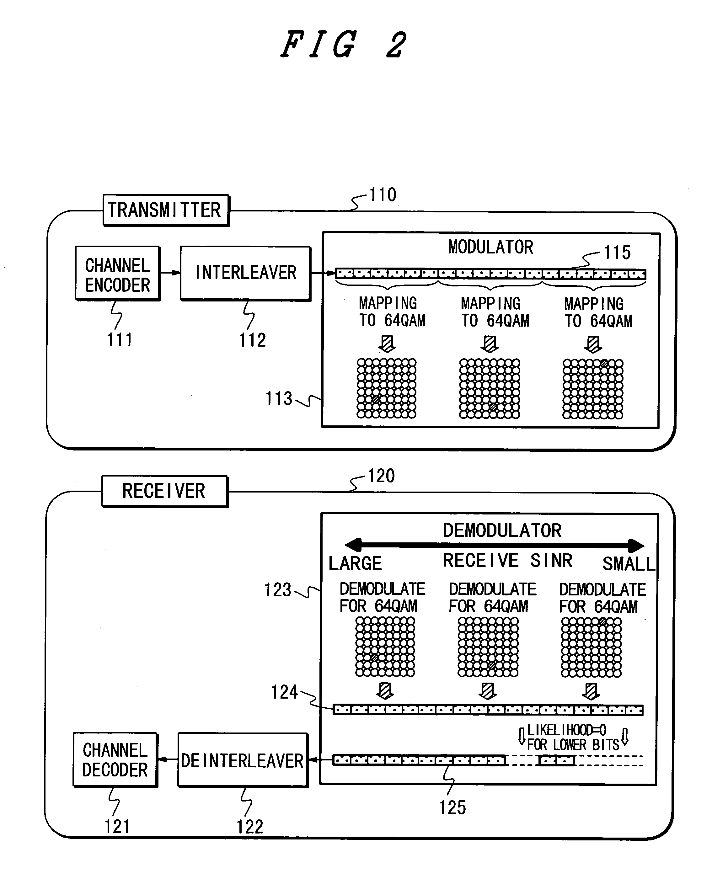
[0013] Also, to achieve the above object, in a communication system according to a second aspect of the present invention, a transmitter and a receiver share a maximum number of transmission bits per symbol as a parameter. The transmitter modulates an encoded and interleaved transmission signal in accordance with a modulation scheme which enables the transmission of one or more bits per symbol. When the number of bits per symbol which can be modulated by the modulation scheme is below the maximum number of transmission bits per symbol, the transmitter discards the remaining bits and modulates the next symbol. The receiver demodulates a received signal in accordance with a modulation scheme which enables the transmission of one or more bits per symbol. The receiver reduces the absolute value of a likelihood of a signal corresponding to a bit assigned to a lower bit of a symbol in accordance with the channel quality before deinterleaving and decoding the signal subsequent to the demodulation, thereby making it possible to switch the number of bits communicated per symbol in accordance with variations in the situation on a channel, without the need for communicating information on the modulation scheme between the transmitter and receiver.
[0014] Further, in the first and second aspects of the present invention in common, the receiver notifies the transmitter whether or not a signal has been successfully decoded. When notified that the signal has been unsuccessfully decoded, the transmitter encodes a codeword based on the same information as that used to encode the signal which has been unsuccessfully decoded, as notified thereto, and transmits part of the codeword which has been transmitted or part of the codeword which has not been transmitted, so that a necessary and sufficient amount of information can be transmitted in accordance with the modulation level at which the receiver can actually receive the signal through the channel. The resulting communication system is capable of making communications at an optimal throughput in accordance with variations in the situation on the channel.
[0015] As appreciated from the foregoing, the present invention provides a communication system which can switch the number of bits communicated per symbol in accordance with variations in the situation on a channel, without the need for communicating information on an employed modulation scheme between a transmitter and a receiver, to make communications at an optimal throughput in accordance with variations in the situation on the channel.

Problems solved by technology

Further, when an error occurs in the information on the modulation scheme, the receiver will incorrectly demodulate signals, resulting in a failure of data communication, so that the information on the modulation scheme must be communicated with high accuracy.
In addition, the requirement for correctly matching the modulation scheme between the transmitter and receiver as mentioned above causes a time delay from the measurement of the channel quality to the switching of the modulation scheme, so that the receiver cannot appropriately switch the modulation scheme in response to a sudden change on the channel, thereby failing to sufficiently utilize the channel for communications.

Method used


Image

  • Wireless communication system, and demodulation method and data rate control method therefor
  • Wireless communication system, and demodulation method and data rate control method therefor
  • Wireless communication system, and demodulation method and data rate control method therefor

Examples


Embodiment Construction

[0025] In the following, several embodiments of the present invention will be described with reference to the accompanying drawings. While the following embodiments are described in connection with a scheme which sets a maximum number of transmission bits per symbol to six bits, and employs 64 QAM for modulation in a transmitter and 64 QAM or 16 QAM or QPSK for demodulation in a receiver, the present invention is not limited to such a maximum number of transmission bits or modulation schemes, but can be similarly applied to a more general scheme which sets the maximum number of transmission bits per symbol to 2 m bits, and employs 22m QAM for modulation in a transmitter and 22k QAM (k is a natural number equal to or less than m) for demodulation in a receiver. Also, assume in the foregoing that when k=1, 4 QAM represents the same modulation scheme as QPSK.

[0026]FIG. 1 illustrates a schematic diagram which represents a first implementation of a modulation / demodulation method in the ...


PUM


Abstract

A transmitter and a receiver share a maximum number of transmission bits per symbol as a parameter. The transmitter modulates an encoded and interleaved transmission signal in accordance with a modulation scheme which enables the transmission of one bit or more per symbol, while the receiver demodulates a received signal based on a channel quality in accordance with a modulation scheme which has a higher modulation level as the channel quality is higher. When the number of demodulated bits per symbol is smaller than the maximum number of transmission bits per symbol, the receiver deinterleaves and decodes a received signal after the demodulation on the assumption that the received signal has likelihoods of zero as much as the number of missing bits.

Description

BACKGROUND OF THE INVENTION [0001] 1. Field of the Invention [0002] The present invention relates to a wireless communication system which relies on multi-valued modulation for transmitting an error correcting code and information of one bit or more per symbol, and a demodulation method and a data rate control method associated with the wireless communication system for improving the reception quality when the gain, interference, and / or noise power vary on a channel. [0003] 2. Description of the Related Art [0004] The multi-valued modulation has been known for transmitting information of a plurality of bits per symbol in order to increase the transmission amount per unit time in a wireless communication system. [0005] The multi-valued modulation exhibits a higher maximum throughput on a channel of high quality as the number of bits per symbol increases, but experiences a largely reduced throughput, if the channel is degraded in quality, as the number of bits per symbol increases. Th...

Claims


Application Information

Patent Timeline
IPC IPC(8): H04L27/18H04B7/26H04L1/16H04L27/00H04L27/34
CPCH04L27/34H04L27/3488H04B7/26
Inventor TAMAKI, SATOSHIHANAOKA, SEISHIYANO, TAKASHI
Owner HITACHI LTD
Learn More