Removable vein filter

a filter and vein technology, applied in the field of vein filter, can solve the problems of shock and even death, interference with oxygenation of blood, and limited use of medications,

Inactive Publication Date: 2005-03-10
ARGON MEDICAL DEVICES
View PDF99 Cites 61 Cited by
  • Summary
  • Abstract
  • Description
  • Claims
  • Application Information

AI Technical Summary

Benefits of technology

[0013] The present invention overcomes the disadvantages and deficiencies of the prior art by providing a removable vessel filter comprising first and second filtering portions and first and second anchoring portions. A transverse dimension of the first filtering portion in an expanded configuration is less than a transverse dimension of the first anchoring portion in an expanded configuration, and a transverse dimension of the second filtering portion is less than a transverse dimension of the second anchoring portion. The first and second filtering portions are positioned closer to each other than the first and second anchoring portions, and the anchoring portions are formed on first and second opposite portions of the vessel filter. The vessel filter is removable from a vessel wall by engagement of either the first filtering portion or the second filtering portion.

Problems solved by technology

These clots typically originate in the veins of the lower limbs and can migrate through the vascular system to the lungs where they can obstruct blood flow and therefore interfere with oxygenation of the blood.
Pulmonary embolisms can also cause shock and even death.
These medications, however, have limited use since they may not be able to be administered to patients after surgery or stroke or given to patients with high risk of internal bleeding.
Also, this medication approach is not always effective in preventing recurring blood clots.
However, this approach is an invasive surgical procedure, requiring an abdominal incision and general anesthesia and frequently causing vessel thrombosis and lower extremity swelling.
Also, there is a lengthy patient recovery time and additional hospital and surgeon expenses associated with this major surgery.
In fact, oftentimes, the patients requiring the surgery are unhealthy and the major surgery and general anesthesia poses a risk in and of itself.

Method used


Image

  • Removable vein filter
  • Removable vein filter
  • Removable vein filter

Examples


Embodiment Construction

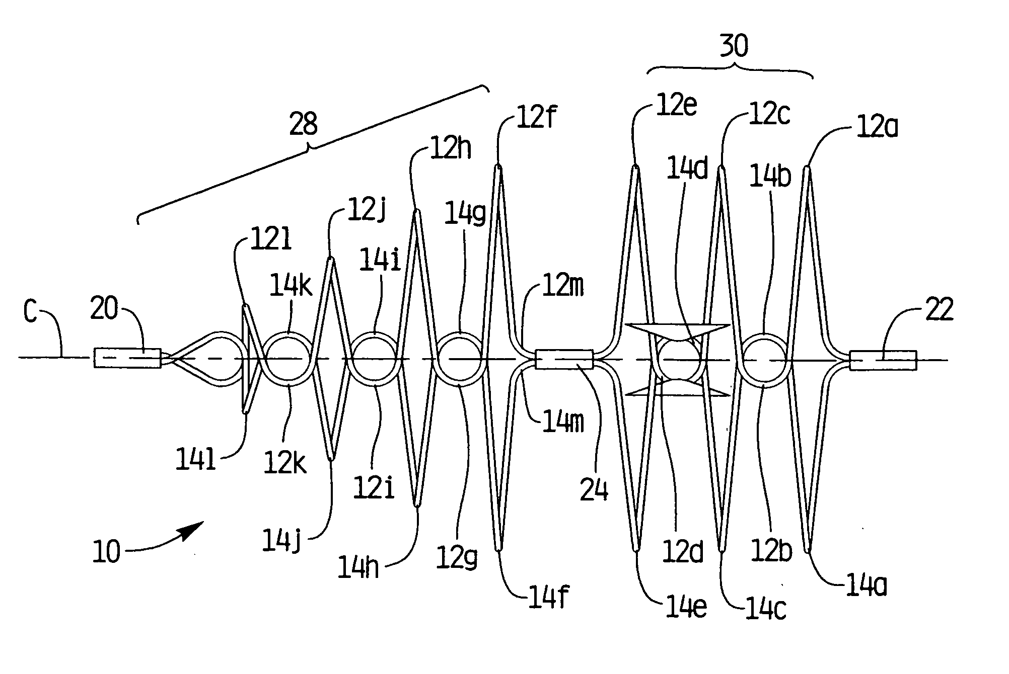
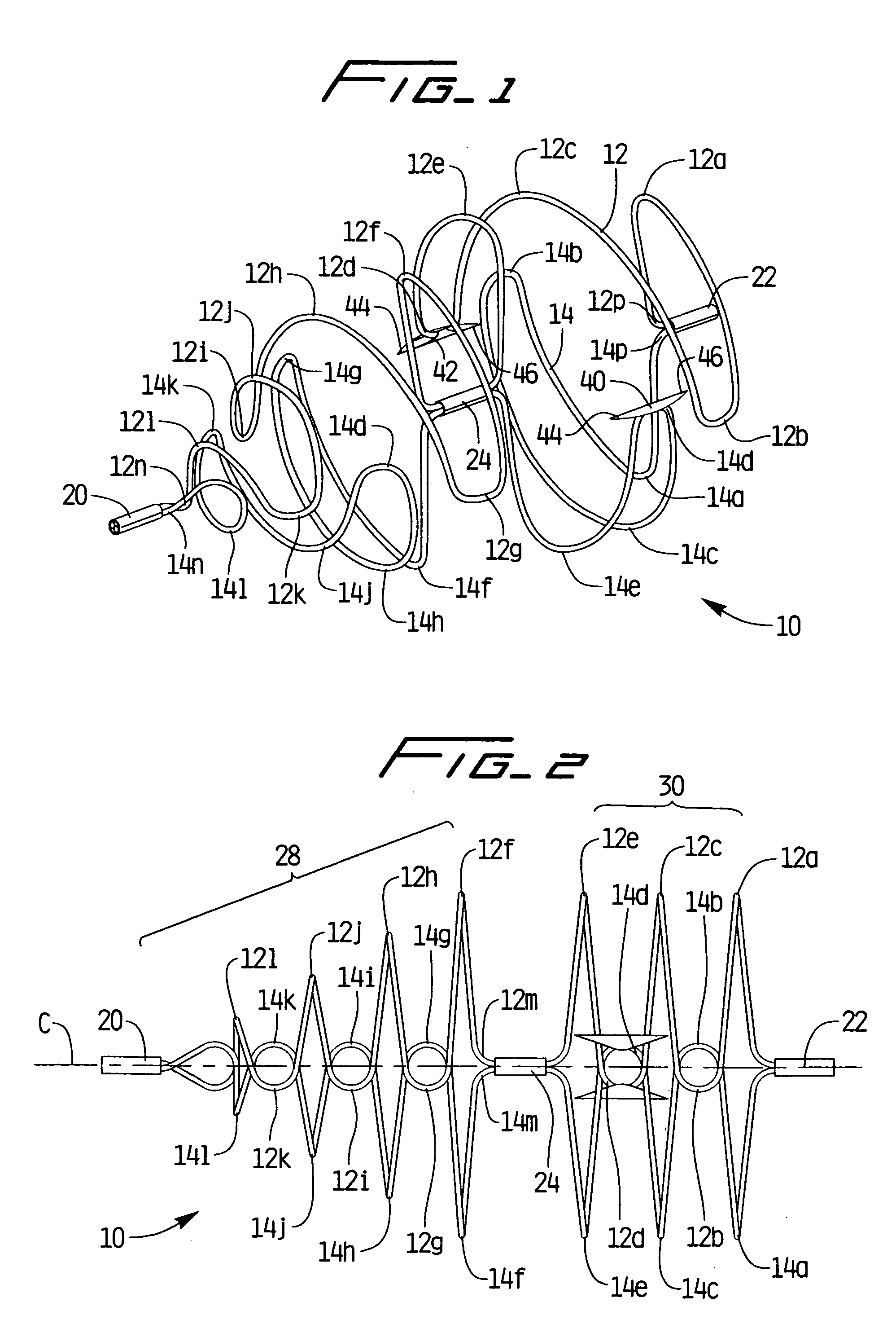
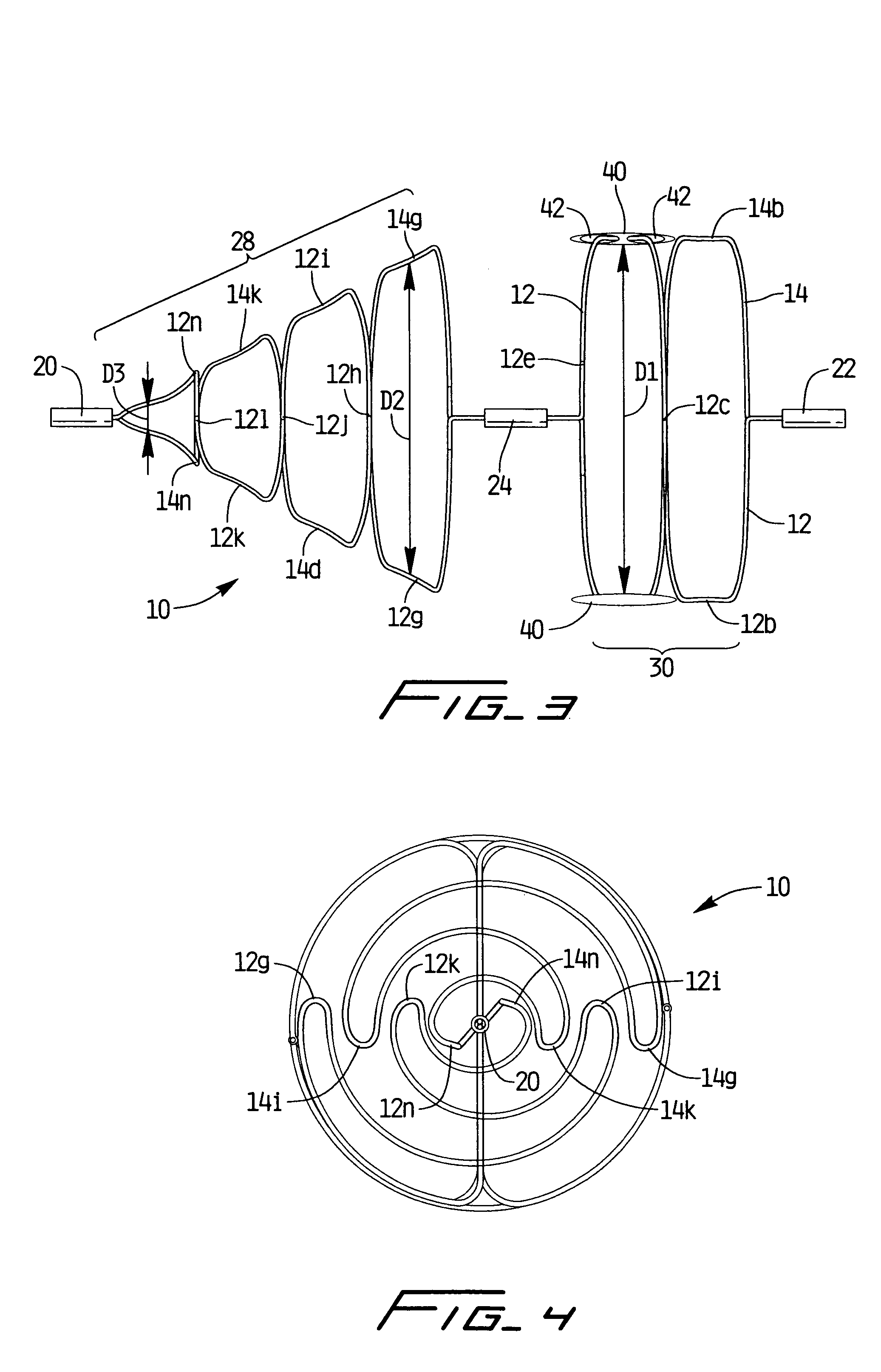
[0094] Turning now to the drawings, wherein like reference numerals identify similar or like components throughout the several views, several embodiments of vein filters of the present invention are described for placement within the inferior vena cava to capture blood clots or other particles which could otherwise pass to the lungs. These filters are movable from a low profile collapsed configuration to facilitate insertion through the delivery sheath to an expanded position to enable the anchoring members to atraumatically contact the vessel walls to secure (mount) the filter within the inferior vena cava. The anchoring members are configured to securely retain the filter in the vessel while allowing for disengagement from the vessel wall, if desired, to enable removal of the filter. The wire(s) which form the vein filters of the present invention are looped to form an anchoring portion and a narrowed filtering portion, as will be described in detail below.

[0095] With reference f...


PUM


Abstract

The present provides a removable vessel filter comprising a first and second filtering portion and a first and second anchoring portion, wherein a transverse dimension of the first filtering portion in an expanded configuration is less than a transverse dimension of the first anchoring portion in an expanded configuration, and a transverse dimension of the second filtering portion is less than a transverse dimension of the second anchoring portion. The first and second filtering portions are positioned closer to each other than the first and second anchoring portions, and the anchoring portions being formed on first and second opposite portions of the vessel filter. The vessel filter is removable from a vessel wall by engagement of either the first filtering portion or the second filtering portion.

Description

[0001] This application is a continuation-in part-of application Ser. No. 09 / 883,819, filed Jun. 18, 2001 and a continuation-in-part of application Ser. No 09 / 883,818, filed Jun. 18, 2001, the entire contents of both applications are incorporated herein by reference.BACKGROUND [0002] 1. Technical Field [0003] This application relates to a vascular filter and more particularly to a vein filter for capturing blood clots within the vessel. [0004] 2. Background of Related Art [0005] Passage of blood clots to the lungs is known as pulmonary embolism. These clots typically originate in the veins of the lower limbs and can migrate through the vascular system to the lungs where they can obstruct blood flow and therefore interfere with oxygenation of the blood. Pulmonary embolisms can also cause shock and even death. [0006] In some instances, blood thinning medication, e.g. anticoagulants such as Heparin, or sodium warfarin can be given to the patient. These medications, however, have limite...

Claims


Application Information

Patent Timeline
Patent Type & Authority Applications(United States)
IPC IPC(8): A61B17/00A61F2/01
CPCA61F2/01A61F2002/011A61F2002/016A61F2230/0091A61F2230/0067A61F2230/0078A61F2230/008A61F2230/0006A61F2/011
Inventor MCGUCKIN, JAMES F. JR.BRIGANTI, RICHARD T.HINCHLIFFE, PETER W.J.
Owner ARGON MEDICAL DEVICES
Why Eureka
Try Eureka