Flow reducing implant

US20050055082A1Inactive Publication Date: 2005-03-10NEOVASC MEDICAL LTD

Image

  • Flow reducing implant
  • Flow reducing implant
  • Flow reducing implant

Examples


Embodiment Construction

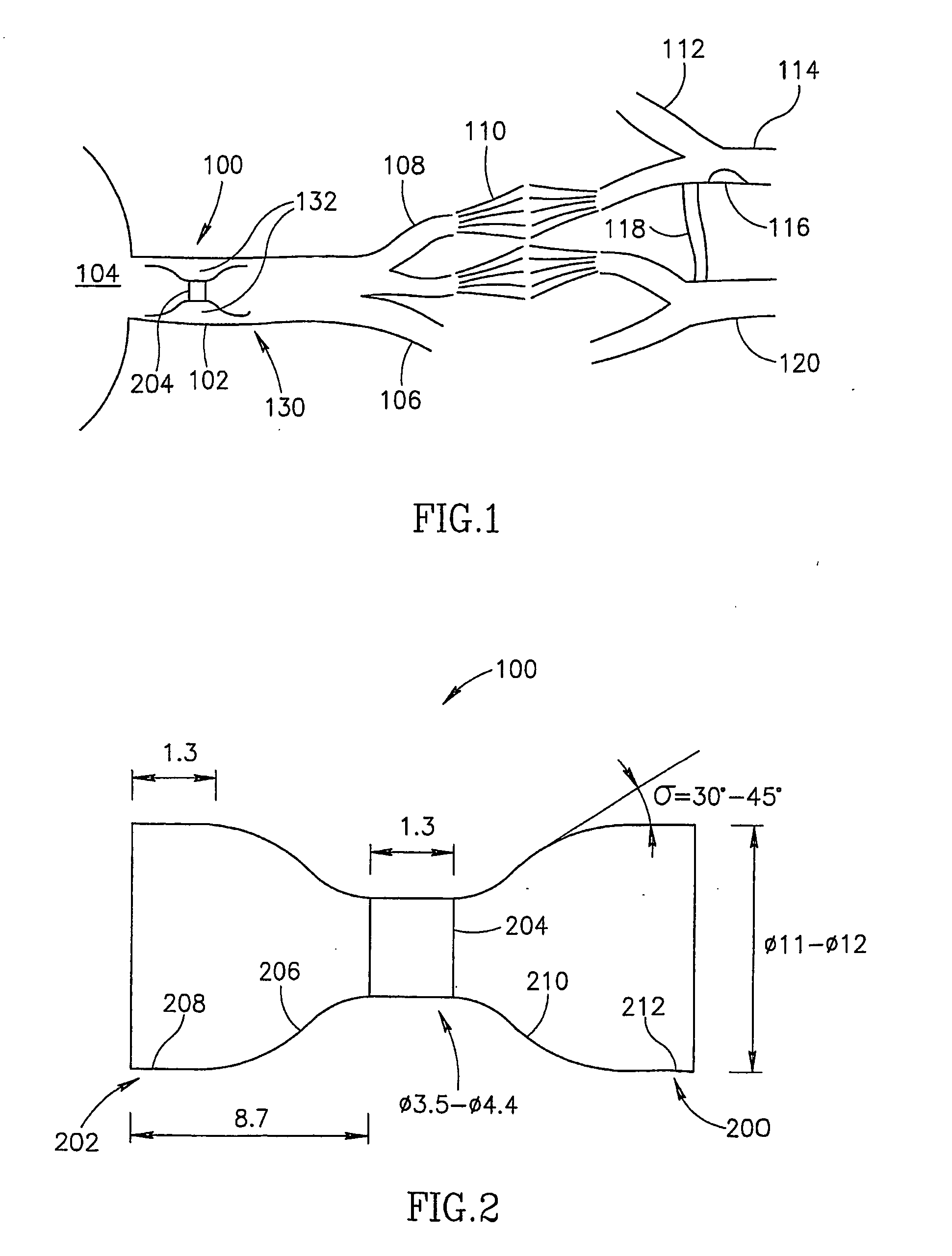
[0125]FIG. 1 is a schematic showing of a flow reducing implant 100 installed in a coronary sinus vein 102, in accordance with an exemplary embodiment of the invention. Coronary sinus 102 drains a plurality of cardiac veins 106 into a right atrium 104. The cardiac circulation is generally hierarchical and comprises of stages of reducing (or increasing) diameter. Thus, veins 106, in turn, drain a plurality of thin venoules 108, which, after a few stages, drain a plurality of capillaries 110. Capillary 110 is fed by a plurality of arterioles 112, which, after a few stages, are fed by a plurality of coronary arteries 114 and 120. A stenosis 116 is shown in a coronary artery 114. While the cardiac circulation is generally hierarchical, some connection exists between different branches. Occasionally, the existence of stenosis 116 will cause a collateral connection 118 to spontaneously form (or widen an existing connection) between coronaries 114 and 120, bypassing stenosis 116.

[0126] In ...


PUM


Abstract

A flow reducing implant for reducing blood flow in a blood vessel having a cross sectional dimension, the flow reducing implant comprising a hollow element adapted for placement in the blood vessel defining a flow passage therethrough, said flow passage comprising at least two sections, one with a larger diameter and one with a smaller diameter, wherein said smaller diameter is smaller than a cross section of the blood vessel. A plurality of tabs anchor, generally parallel to the blood vessel wall, are provided in some embodiments of the invention.

Description

RELATED APPLICATIONS [0001] This application is a continuation-in-part of U.S. application Ser. No. 09 / 534,968, filed Mar. 27, 2000 and a continuation-in-part of PCT application PCT / L01 / 00284, filed Mar. 27, 2001, which designates the US and which published in English, the disclosures of which are incorporated herein by reference. This application also claims the priority of Israel applications 145750, filed Oct. 4, 2001 and 151162, filed Aug. 8, 2002, the disclosure of which are incorporated herein by reference.FIELD OF THE INVENTION [0002] The present invention relates to implants for reducing flow through bodily conduits, for example, blood vessels. BACKGROUND OF THE INVENTION [0003] The heart pumps blood through the body. The heart itself is fed by coronary arteries that end at capillaries. The capillaries are drained by a network of coronary veins, that (typically) flow into a vein known as the coronary sinus. The coronary sinus is a short, large diameter vein that is substanti...

Claims


Application Information

Patent Timeline
10 Mar 2005
Publication
US20050055082A1
IPC
A61B; A61B17/00; A61F2/00; A61M29/02
CPC
A61F2/91; A61F2/958; A61F2002/068; A61F2002/91525; A61F2002/91533; A61F2002/9155; A61F2002/91575; A61F2250/0018
Inventors
BEN MUVHAR, SHMUEL; SHALEV, ILAN