Regeneration control of diesel particulate filter

a technology of particulate filter and regeneration control, which is applied in the direction of electrical control, exhaust treatment electric control, separation process, etc., can solve the problems of large electrical energy consumption during regeneration of dpf, inability to remove all of the particulate matter, and high degree of precision, and achieve the effect of not consuming energy

Inactive Publication Date: 2005-03-17
NISSAN MOTOR CO LTD
View PDF5 Cites 24 Cited by
  • Summary
  • Abstract
  • Description
  • Claims
  • Application Information

AI Technical Summary

Benefits of technology

[0008] It is therefore an object of this invention to estimate an amount of remaining particulate matter with a high degree of precision and without consuming energy.

Problems solved by technology

However, the operating condition of a diesel engine for a vehicle varies constantly, and hence it is not always possible to remove all of the particulate matter trapped in the DPF in one regeneration operation.
If particulate matter trapping is resumed in a partially regenerated state, errors are likely to occur when estimating the amount of particulate matter trapped in the DPF in order to determine the next regeneration timing.
In this prior art, however, a heater and a pump for supplying the regeneration gas must be used every time the amount of remaining particulate matter is estimated, and hence a large amount of electrical energy is consumed during regeneration of the DPF.

Method used


Image

  • Regeneration control of diesel particulate filter
  • Regeneration control of diesel particulate filter
  • Regeneration control of diesel particulate filter

Examples


second embodiment

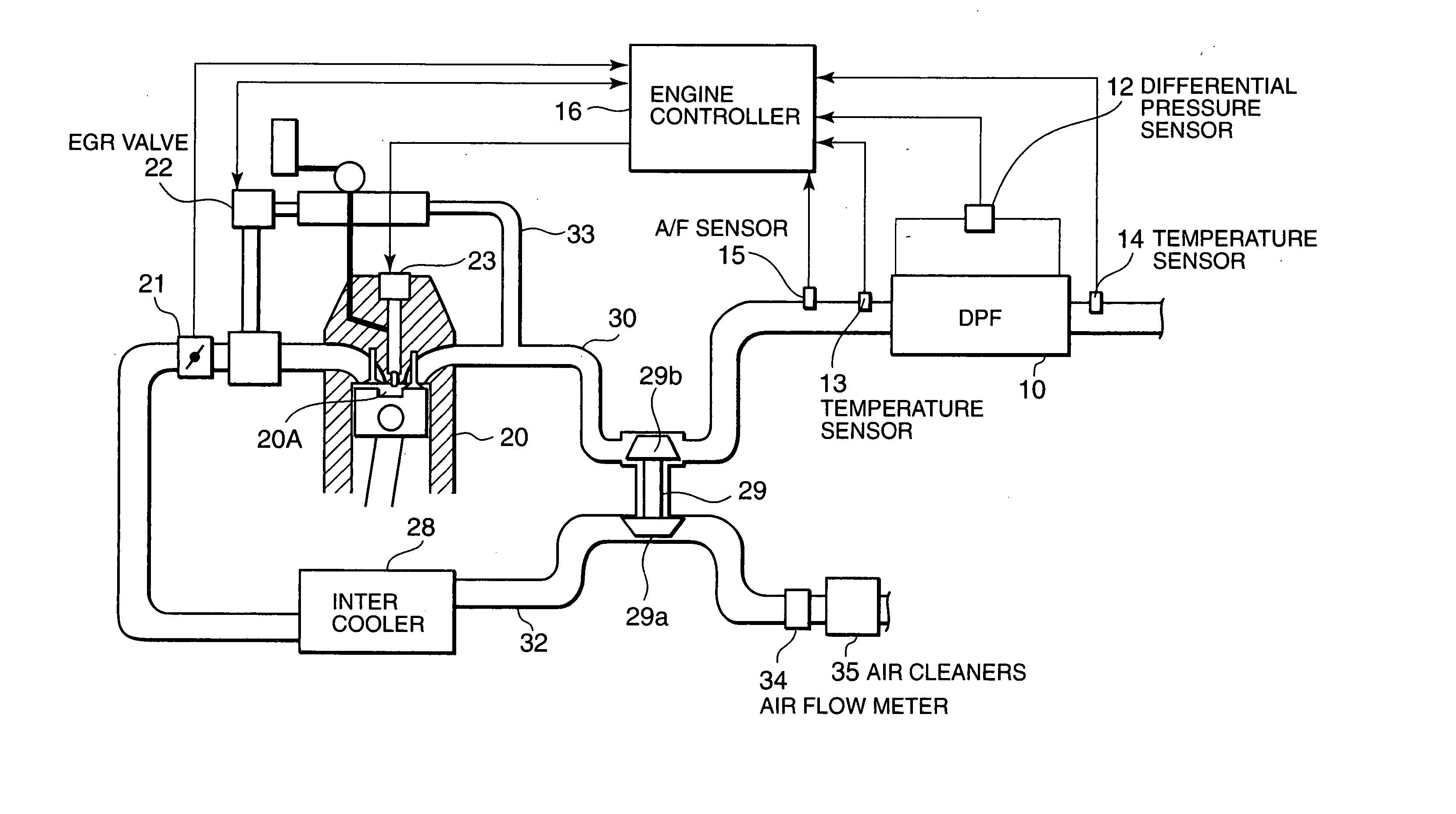
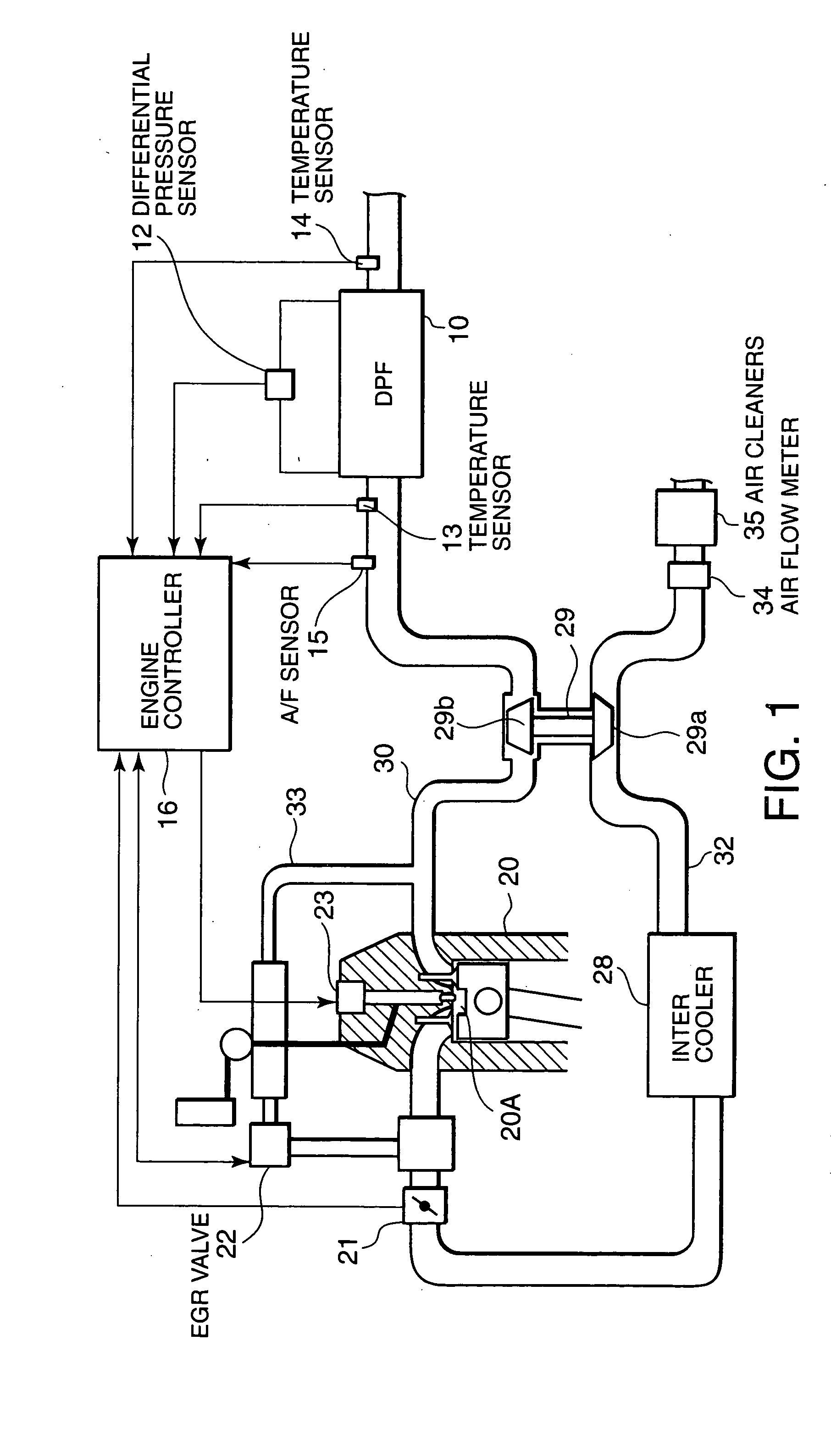
[0052] Next, referring to FIGS. 6 and 7, this invention will be described.

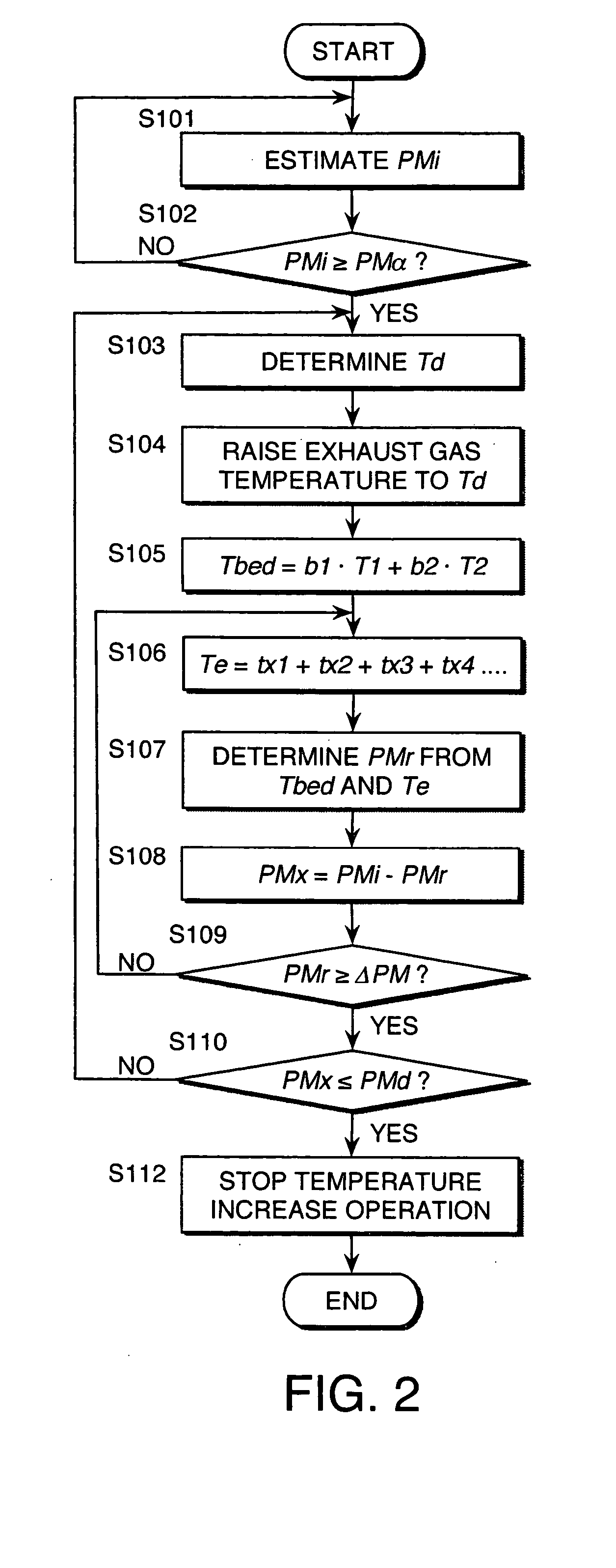
[0053] The hardware constitution of this embodiment is identical to that of the first embodiment. The engine controller 16 according to this embodiment also executes the routine in FIG. 2. In this embodiment, however, the processing content of the step S106 in FIG. 2 differs from that of the first embodiment.

first embodiment

[0054] In the step S106 in the first embodiment, the effective regeneration time Te is calculated as a cumulative value of the time during which the bed temperature Tbed of the DPF 10 exceeds the target bed temperature Tx.

[0055] As noted above, the target bed temperature Tx is the temperature at which the particulate matter is burned reliably, but even when the bed temperature Tbed of the DPF 10 does not reach the target bed temperature Tx, a part of the particulate matter can be burned as long as the bed temperature Tbed exceeds a temperature allowing combustion of the particulate matter. Hence in this embodiment, the amount of remaining particulate matter is calculated in consideration of the amount of particulate matter that is burned in this temperature region.

[0056] Referring to FIG. 7, in the process of reaching the target bed temperature Tx, the bed temperature Tbed of the DPF 10 passes through successive temperatures Ta, Tb, Tc, Td . . . . Here, the temperature Ta indicates...


PUM

PropertyMeasurementUnit
temperature Txaaaaaaaaaa
temperatureaaaaaaaaaa

Abstract

To regenerate a diesel particulate filter (10) which traps particulate matter contained in the exhaust gas of a diesel engine (20), a controller (16) raises the temperature of the exhaust gas through fuel injection control of a fuel injector (23), and thus burns the particulate matter trapped in the filter (10). The controller (16) cumulatively calculates the time during which the temperature of the filter (10) exceeds a target temperature as an effective regeneration time. By estimating the amount of particulate matter remaining in the filter (10) on the basis of the effective regeneration time, the controller (16) estimates the amount of remaining particulate matter with a high degree of precision and without consuming energy, whereupon regeneration of the filter (10) through fuel injection control ends.

Description

FIELD OF THE INVENTION [0001] This invention relates to regeneration control of a filter which traps particulate matter contained in the exhaust gas of a diesel engine. BACKGROUND OF THE INVENTION [0002] A diesel particulate filter (hereinafter referred to as DPF) which traps particulate matter contained in the exhaust gas of a diesel engine for a vehicle performs regeneration by burning the trapped particulate matter when the amount of trapped particulate matter reaches a certain level, and thus becomes able to trap particulate matter again. [0003] Known methods for burning the particulate matter include a method of raising the temperature of the exhaust gas by fuel injection control, and a method of raising the temperature of the DPF using a heater. SUMMARY OF THE INVENTION [0004] However, the operating condition of a diesel engine for a vehicle varies constantly, and hence it is not always possible to remove all of the particulate matter trapped in the DPF in one regeneration ope...

Claims


Application Information

Patent Timeline
Patent Type & Authority Applications(United States)
IPC IPC(8): F02D45/00B01D46/42F01N3/02F01N3/035F01N9/00F02B37/00F02D41/02
CPCF01N3/035F01N9/002F02B37/00Y02T10/47F02D41/1446F02D2200/0804F02D2200/0812F02D41/029Y02T10/40
Inventor OTAKE, MAKOTOKAWASHIMA, JUNICHITSUTSUMOTO, NAOYAKONDOU, TERUNORIINOUE, TAKAOUENO, SHOUICHIROUKOGA, TOSHIMASA
Owner NISSAN MOTOR CO LTD
Why Eureka
Try Eureka