
Defogger line forming device

a technology of defogger and resin window, which is applied in the direction of liquid surface applicators, coatings, special surfaces, etc., can solve the problems of difficult to make the thickness and width of the conductive paste uniform, the effect of defogger upon energization is rather low, and the inability to adopt screen printing in imparting conductive pas

Inactive Publication Date: 2005-03-17
TOYOTA IND CORP
View PDF8 Cites 29 Cited by
  • Summary
  • Abstract
  • Description
  • Claims
  • Application Information

AI Technical Summary

Problems solved by technology

However, in the case of a resin glass, the window is normally formed from the beginning into a curved shape by injection molding, so that it is impossible to adopt screen printing in imparting the conductive paste as in the case of inorganic glass.
However, such a low-temperature baking type conductive paste exhibits a high resistance value, so that it has a problem in that the effect of defogger upon energization is rather low.
If, in view of this, an attempt is made to achieve an increase in the cross-sectional area of the conductive paste to thereby reduce the resistance value, it becomes rather difficult to make the thickness and width of the conductive paste uniform, thereby making it difficult to achieve a stable resistance state.
This device, however, cannot be used when applying a paste-like material to a curved object.

Method used


Image

  • Defogger line forming device
  • Defogger line forming device
  • Defogger line forming device

Examples


Embodiment Construction

[0016] An embodiment of the present invention will now be described with reference to the accompanying drawings.

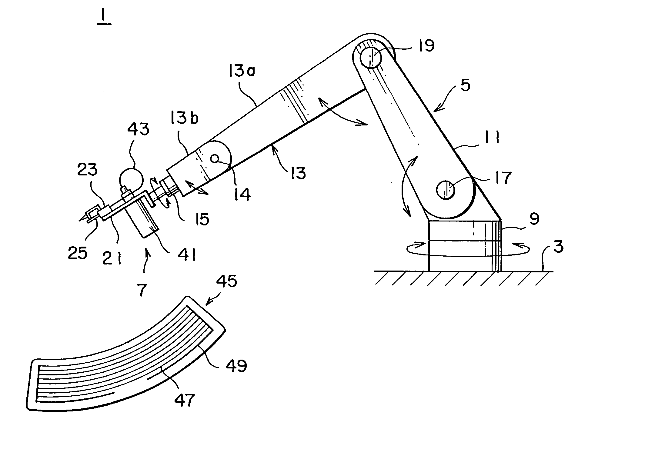
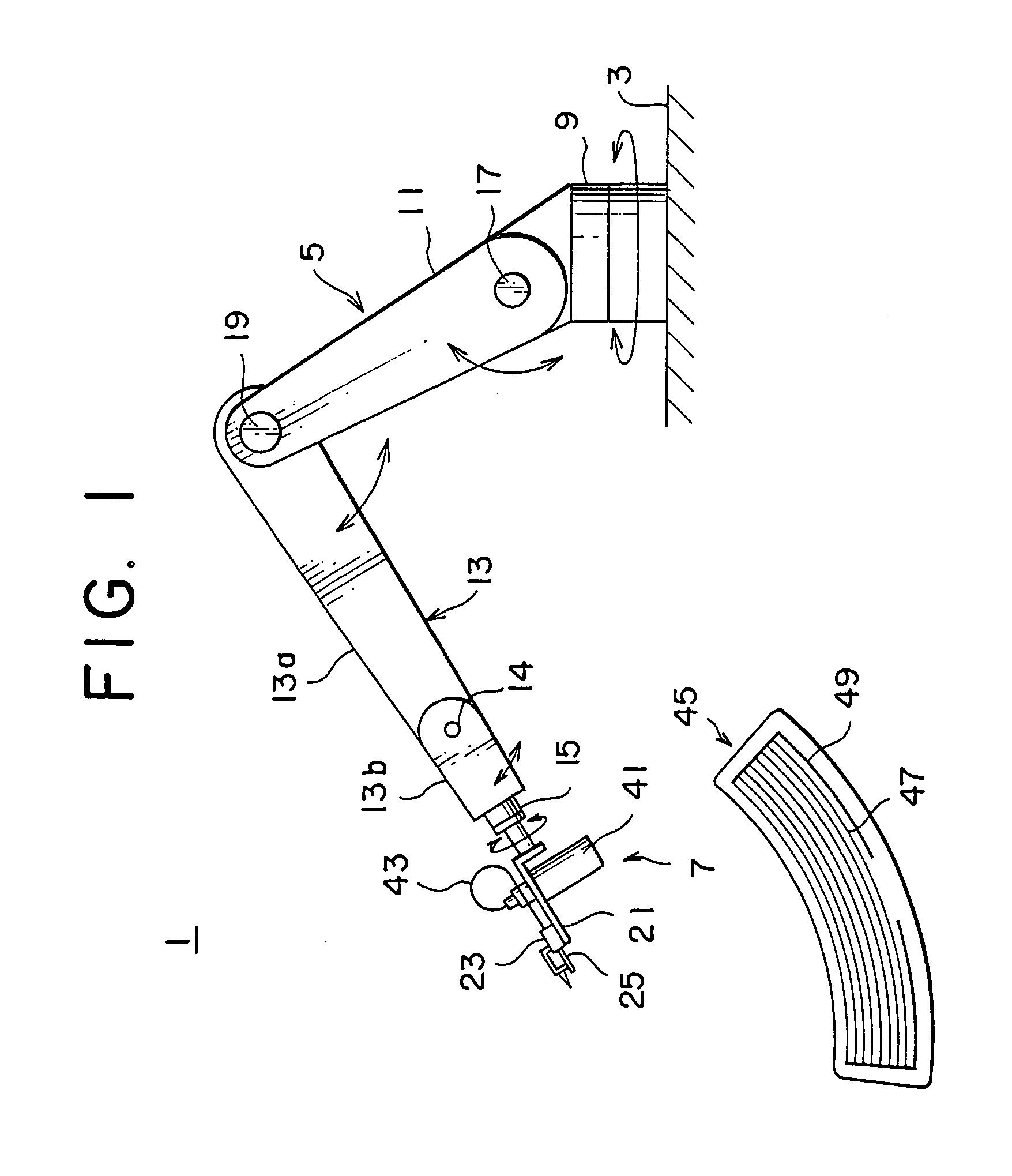
[0017] As shown in FIG. 1, a defogger line forming device 1 is equipped with a robot arm (transfer mechanism) 5 secured to an installation surface 3, and an application head 7 mounted to the distal end of the robot arm 5. The robot arm 5 is mainly equipped with a rotation base 9, a first arm 11, a second arm 13, and a rotation end 15. The lower portion of the rotation base 9 is secured to the installation surface 3, and the lower end of the first arm 11 is secured to the upper portion of the rotation base 9. The upper and lower portions of the rotation base 9 are capable of rotating relative to each other, whereby the first arm 11 is rotatably supported by the rotation base 9. Further, the connection between the proximal end of the first arm 11 and the rotation base 9, and the connection between the proximal end of the second arm 13 and the distal end of the first arm 11 ...


PUM

PropertyMeasurementUnit
Volumeaaaaaaaaaa
Distanceaaaaaaaaaa

Abstract

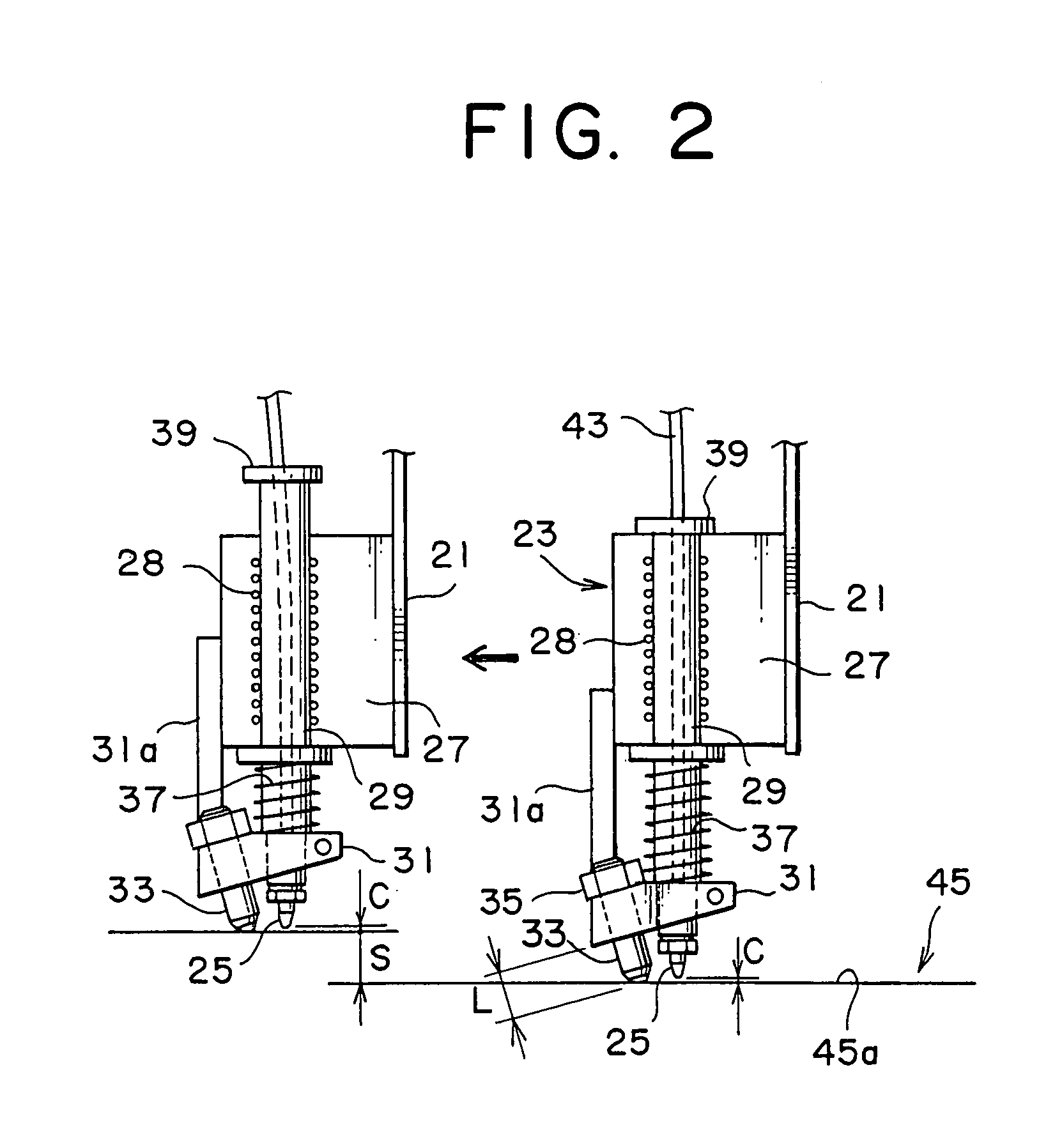
A defogger line forming device is equipped with a nozzle for applying conductive paste to a curved surface resin glass constituting a resin window, a robot arm for moving the nozzle along the window, a contact member provided so as to be movable integrally with the nozzle and adapted to come into contact with the resin window to maintain a fixed distance between the resin window and the nozzle, a volume measurement type supply device for supplying the conductive paste to the nozzle, and a hose communicating with the nozzle and the supply device. More specifically, the nozzle and the contact member are mounted to a bracket at the distal end of the robot arm so as to be slidable in a direction crossing the window, and the supply device is integrally fixed to the bracket.

Description

BACKGROUND OF THE INVENTION [0001] 1. Field of the Invention [0002] The present invention relates to a device for forming the defogger line of a resin window. [0003] 2. Related Background Art [0004] Conventionally, when an automobile rear window formed of inorganic glass is to be provided with a defogger line, it has been common practice to impart a conductive paste constituting a heat line to the surface of the inorganic glass in a flat state by so-called screen printing. Thereafter, heat is applied to perform bending into a curved shaped suitable for an automobile rear window, with the paste being dried by heating at approximately 600° C. [0005] Incidentally, as a result of the recent diversification of automobile rear windows, some rear windows are formed not of inorganic glass but of a resin glass (for example, polycarbonate). However, in the case of a resin glass, the window is normally formed from the beginning into a curved shape by injection molding, so that it is impossible...

Claims


Application Information

Patent Timeline
IPC IPC(8): B05D5/12B05C5/00B05C5/02B05C11/10
CPCB05C5/0216
Inventor IIMORI, YASUSHIKUNO, HIROSHI
Owner TOYOTA IND CORP
Learn More