Conductive paste and grid electrode for silicon solar cells

a solar cell and grid electrode technology, applied in the direction of final product manufacturing, conductors, metal/alloy conductors, etc., can solve the problems of adversely affecting the conversion efficiency of solar cells and reducing yields, and achieve the effect of low palladium content, small invention, and high efficiency of obtained solar cells

Inactive Publication Date: 2009-08-27
EI DU PONT DE NEMOURS & CO
View PDF9 Cites 59 Cited by
  • Summary
  • Abstract
  • Description
  • Claims
  • Application Information

AI Technical Summary

Benefits of technology

[0029]The mean particle diameter (PSD D50) of the specific metal particles is preferably 0.1 to 20 μm.
[0030]Silver may be alloyed with specific metal particles as is described below.
[0031]A specific metal is selected from the group consisting of Pd (palladium), Ir (iridium), Pt (platinum), Ru (ruthenium), Ti (titanium) and Co (cobalt). Two or more metals can be used in combination. Preferably, Pd is used in terms of high efficiency of obtained solar cell.
[0032]The alloy proportions for the alloy are not particularly limited. Amounts of different metals in the alloy is determined by a number of factors. For example, silver and palladium tend to become alloyed no matter what the proportion in which they are blended. Since palladium is more expensive than silver, a lower palladium content is preferable from the standpoint of cost. A Ag:Pd alloy with wt % Pd preferably between 1 and 30%, more preferably between 5 and 20% may be used.
[0033]The alloys of the present invention can be produced by methods known in the art. Commercially available alloys may also be used.
[0034]The alloy content is preferred to be 0.01 to 20 wt %, preferably 0.05 to 10 wt %, based on the total amount of the weight of the paste. If the amount of specific metal is excessively low, the advantage of the present invention becomes small. In addition, if the amount of specific metal is excessively high, conductor resistance increases, fireability decreases and costs increase.

Problems solved by technology

However, a certain degree of variation in temperature can occur in firing furnaces, which can adversely affect the solar cell conversion efficiency.
When large-scale firing furnaces are used, requiring a narrow temperature range leads to lower yields.

Method used


Image

  • Conductive paste and grid electrode for silicon solar cells
  • Conductive paste and grid electrode for silicon solar cells
  • Conductive paste and grid electrode for silicon solar cells

Examples


examples

[0067]1) 10 parts ethyl cellulose resin was added to 90 parts terpineol, the mixture was stirred and dissolved for about 2 hours while heated to 80° C., and the solution was then allowed to stand until returned to room temperature, giving a binder solution.

[0068]2) 50 parts Pd powder was mixed into 50 parts of the ethyl cellulose resin solution of 1), and the mixture was kneaded with 3 rolls, giving a Pd paste.

[0069]3-1) 3 parts of the Pd paste of 2) was added to 100 parts solar cell paste PV145 (Ag paste) by DuPont, and the mixture was stirred to homogeneity in a defoaming stirrer, giving a paste A.

[0070]3-2) 50 parts PV145 was added to 50 parts of paste A, and the mixture was stirred to homogeneity in a defoaming stirrer, giving paste B.

[0071]3-3) 50 parts of PV145 was added to 50 parts of the paste B, and the mixture was stirred to homogeneity in a defoaming stirrer, giving paste C.

[0072]3-4) 50 parts of PV145 was added to 50 parts of the paste C, and the mixture was stirred to h...


PUM

PropertyMeasurementUnit
widthaaaaaaaaaa
temperaturesaaaaaaaaaa
particle diameteraaaaaaaaaa

Abstract

A conductive paste for grid electrodes in solar cells includes a conductive component, glass frit, and resin binder, wherein the conductive component is selected from the group consisting of (i) silver particles and metal particles selected from the group consisting of Pd, Ir, Pt, Ru, Ti, and Co, (ii) alloy particles comprising silver and metal selected from the group consisting of Pd, Ir, Pt, Ru, Ti, and Co, and (iii) silver particles and core-shell particles in which a metal selected from the group consisting of Pd, Ir, Pt, Ru, Ti, and Co is coated on the surface of silver or copper.

Description

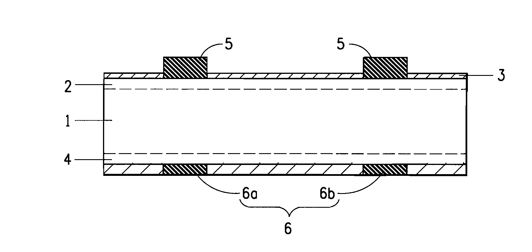
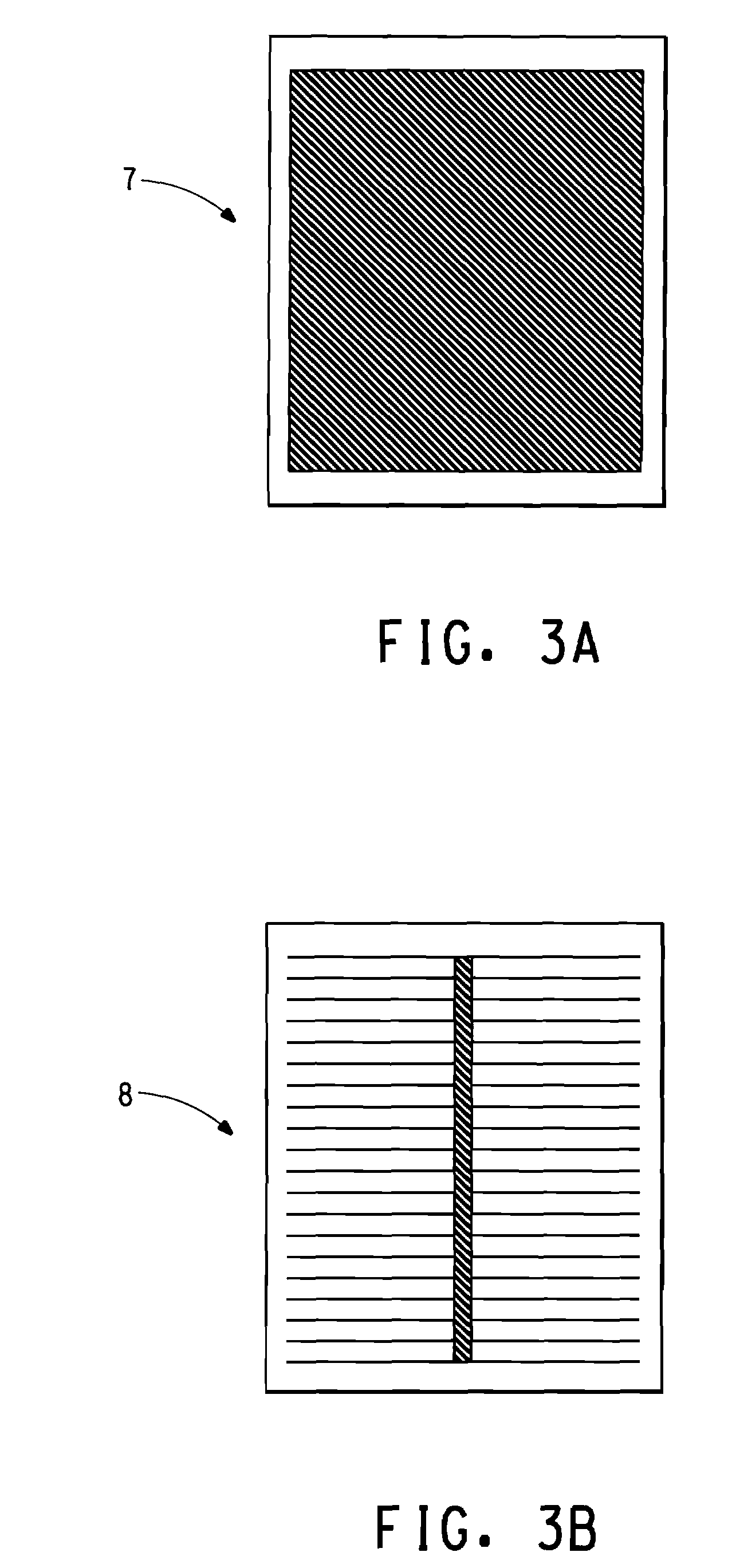
BACKGROUND OF INVENTION[0001]1. Field of the Invention[0002]The present invention relates to a conductive paste for a solar cell, and more particularly, to an electrically conductive paste used to form grid electrodes for Si solar cell.[0003]2. Technical Background[0004]Silver paste is widely used for the electrode paste used in silicon solar cells, since electrode pastes for solar cells are required to have low electrical resistance to facilitate improved efficiency.[0005]In the case of silicon solar cells in which electrodes are formed on both sides, the light receiving side paste usually contains, as basic components, electrically conductive particles in the form of Ag, binder, glass frit and a solvent (see, for example, Japanese Patent Application Laid-open No. 2006-295197). Silver is generally used as the metal powder for grid electrodes in solar cells. In Japanese Patent Application Laid-open No. 2006-295197, examples of electrically conductive particles include metal particle...

Claims


Application Information

Patent Timeline
Patent Type & Authority Applications(United States)
IPC IPC(8): H01L31/04H01B1/02H01L31/18
CPCH01B1/22Y02E10/547H01L31/1804H01L31/022425Y02P70/50
Inventor AKIMOTO, HIDEKI
Owner EI DU PONT DE NEMOURS & CO
Why Eureka
Try Eureka