Shaft drive system for power loom shafts

a technology of shaft drive and power loom, which is applied in the direction of looms, dobbies, textiles and papermaking, etc., can solve the problems of inflexible eccentric looms, inability to create patterns, and shaft looms that cannot achieve the operating speed of eccentric looms, so as to achieve high weaving speeds and reduce the stress on machine components

Active Publication Date: 2005-03-17
GROZ BECKERT KG
View PDF14 Cites 12 Cited by
  • Summary
  • Abstract
  • Description
  • Claims
  • Application Information

AI Technical Summary

Benefits of technology

[0015] With this kind of coupling system as well, the drive system of a heddle shaft can be switched on and off without slowing down or shutting off the rotary drive mechanism of the input shaft. Overall, a harmonic or nearly harmonic motion of the heddle shaft is generated not only during weaving, but also upon switching the heddle shaft on and off. This creates the preconditions for high weaving speeds, with only little stress on the machine components involved.

Problems solved by technology

However, such eccentric looms are inflexible.
Only to a limited extent is it possible to create patterns or different kinds of bindings.
However, such shaft looms cannot attain the operating speed of eccentric looms.
The function of the pawl indexing mechanisms is vulnerable to wear.
Increasing the operating speed, however, not only causes pawl wear but also leads to breakage of heddles and shafts.

Method used


Image

  • Shaft drive system for power loom shafts
  • Shaft drive system for power loom shafts
  • Shaft drive system for power loom shafts

Examples


Embodiment Construction

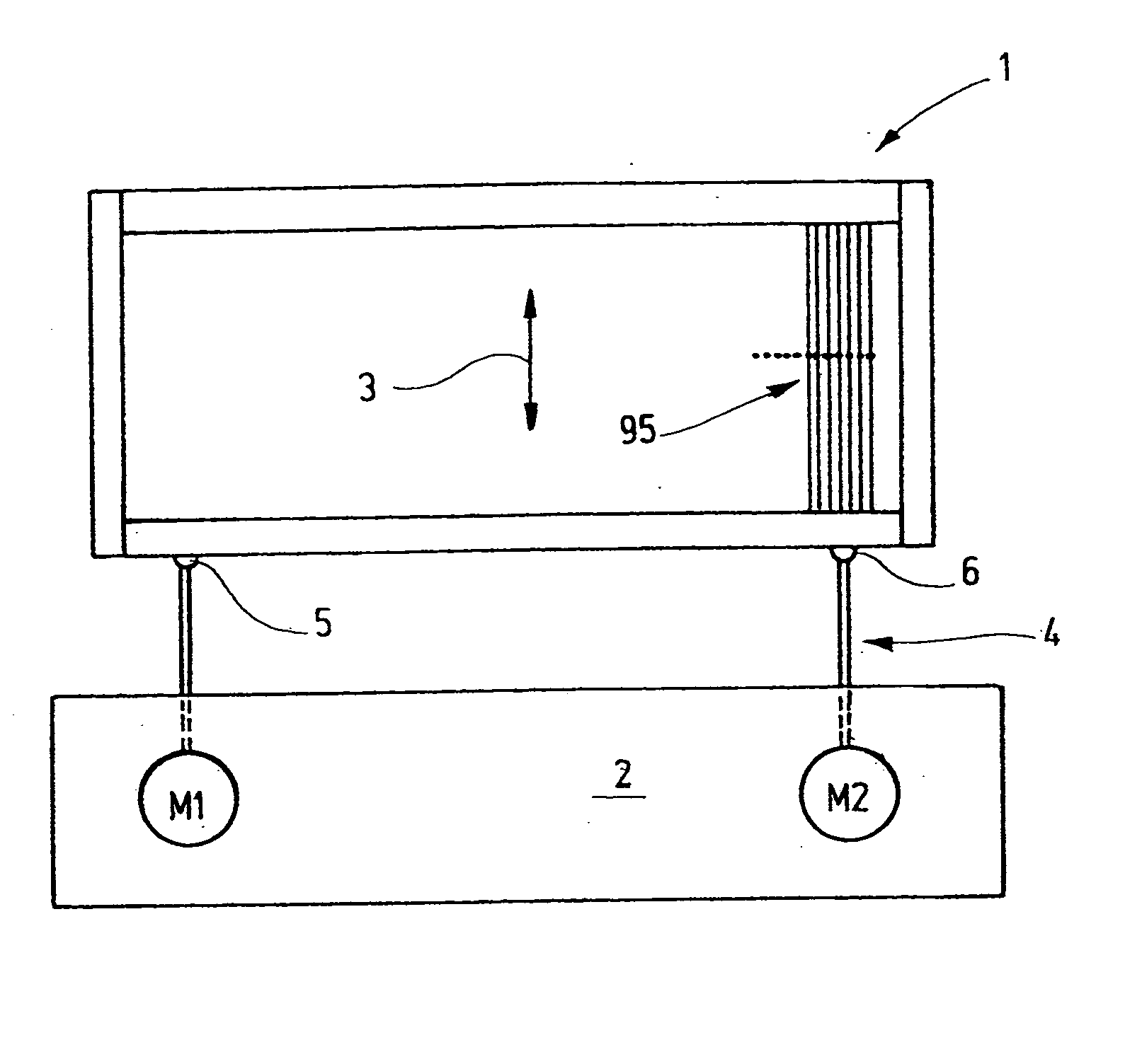
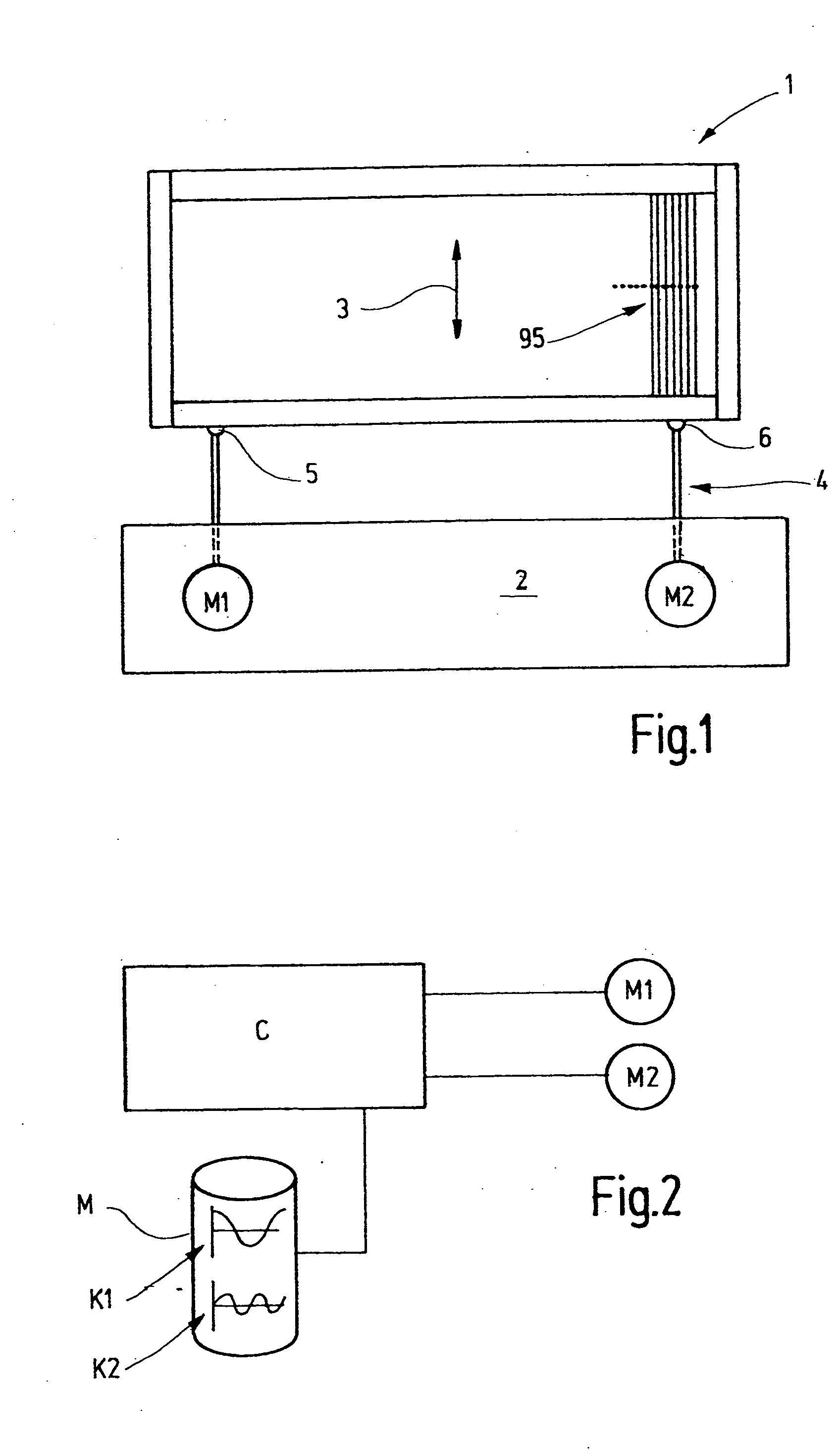
[0030] In FIG. 1, a heddle shaft 1 with an associated shaft drive system 2 is shown. The heddle shaft 1 is formed by a frame which is provided with heddles 95 and which is moved up and down during operation, as indicated by an arrow 3. A rod linkage 4 is used for driving purposes; it is attached to the heddle shaft 1 at two or more points 5, 6 and forms the power takeoff mechanism of the shaft drive system 2. The shaft drive system 2 includes one or more drive sources, for instance in the form of motors M1, M2. These motors are for instance electric servomotors, which are connected to the rod linkage 4 via a spindle lifting gear, a belt gear, or some other gear that converts the rotary motion of the motors into a linear motion. Alternatively, linear motors, linear stepping motors, or the like may be used. In some cases, a single motor suffices, while in others, two or more motors are required.

[0031] The motors M1, M2 are controlled by a control unit C, based on a microcontroller, f...


PUM


Abstract

A novel shaft gear for harmonious engagement and disengagement of individual heddle shafts and for deriving their motion from the rotary motion of a single input shaft has a coupling system with two input elements. While one of the input elements serves to drive the output element of the coupling system permanently, the other input element serves solely to synchronize the output element briefly with the first input element. The switchover takes place in the brief synchronous phases, in selected angular regions that correspond to the top or bottom reversal point of the heddle shaft. For the switchover, such novel shaft drive mechanisms do not require any stoppage of motion for the input shaft or the shaft drive mechanism.

Description

CROSS REFERENCE TO RELATED APPLICATION [0001] This application claims the priority of German Patent Application No. 103 43 377.5, filed on Sep. 17, 2003, the subject matter of which, in its entirety, is incorporated herein by reference. FIELD OF THE INVENTION [0002] The invention relates to a shaft drive system for at least one heddle shaft of a power loom. BACKGROUND OF THE INVENTION [0003] For forming sheds, power looms are as a rule provided with a plurality of heddle shafts, each of which has many heddles, arranged parallel to one another, through whose the yarn eyelets the warp yarns are passed. For forming sheds, or shedding, the heddle shafts are moved very rapidly up and down. This is accomplished by shaft drive system, which are also called shaft looms or eccentric looms. So-called eccentric looms generate the up-and-down motion of the heddle shafts from the rotary motion of a drive shaft, and high weaving speeds are attainable. However, such eccentric looms are inflexible....

Claims


Application Information

Patent Timeline
Patent Type & Authority Applications(United States)
IPC IPC(8): D03C1/14D03C13/00
CPCD03C1/14D03C13/025D03C13/00D03C1/144D03C9/0683
Inventor BRUSKE, JOHANNESMUNSTER, BERNHARDFALLER, ARMIN
Owner GROZ BECKERT KG
Why Eureka
Try Eureka