Hydraulic pressure controller

a hydraulic unit and controller technology, applied in the direction of braking components, operating means/releasing devices of valves, brake systems, etc., can solve the problems of increased volume (size) of the block, increased cost and weight of the block, and increased cost of the block, so as to facilitate maintenance work of the ecu and the solenoid valve in the hydraulic uni

Inactive Publication Date: 2005-03-17
ADVICS CO LTD
View PDF14 Cites 23 Cited by
  • Summary
  • Abstract
  • Description
  • Claims
  • Application Information

AI Technical Summary

Benefits of technology

[0015] Preferably, a seal member is disposed between the fitting portion and the side surface of the block for sealing any gap present between the fitting portion and the block. The fitting portion i

Problems solved by technology

This leads to increased volume (size) of the block, and thus increased cost and weight of the block.
The block of the hydraulic unit is formed of an expensive material such as an aluminum alloy.
This pushes up the material cost.
Such a small housing may not be capable of accommodating a sufficiently large circuit board.
It is app

Method used


Image

  • Hydraulic pressure controller
  • Hydraulic pressure controller
  • Hydraulic pressure controller

Examples


Embodiment Construction

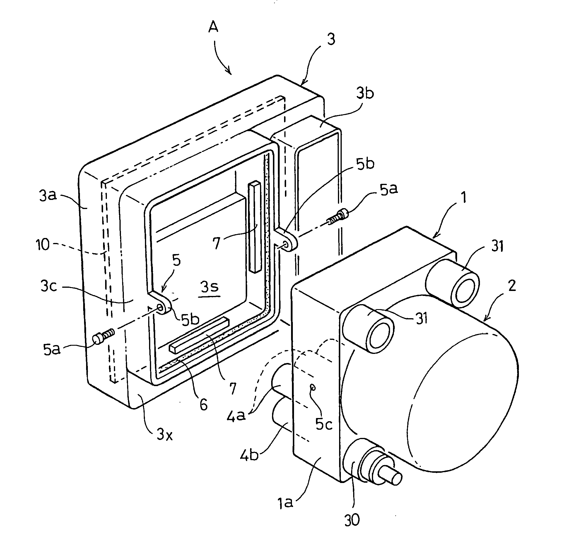
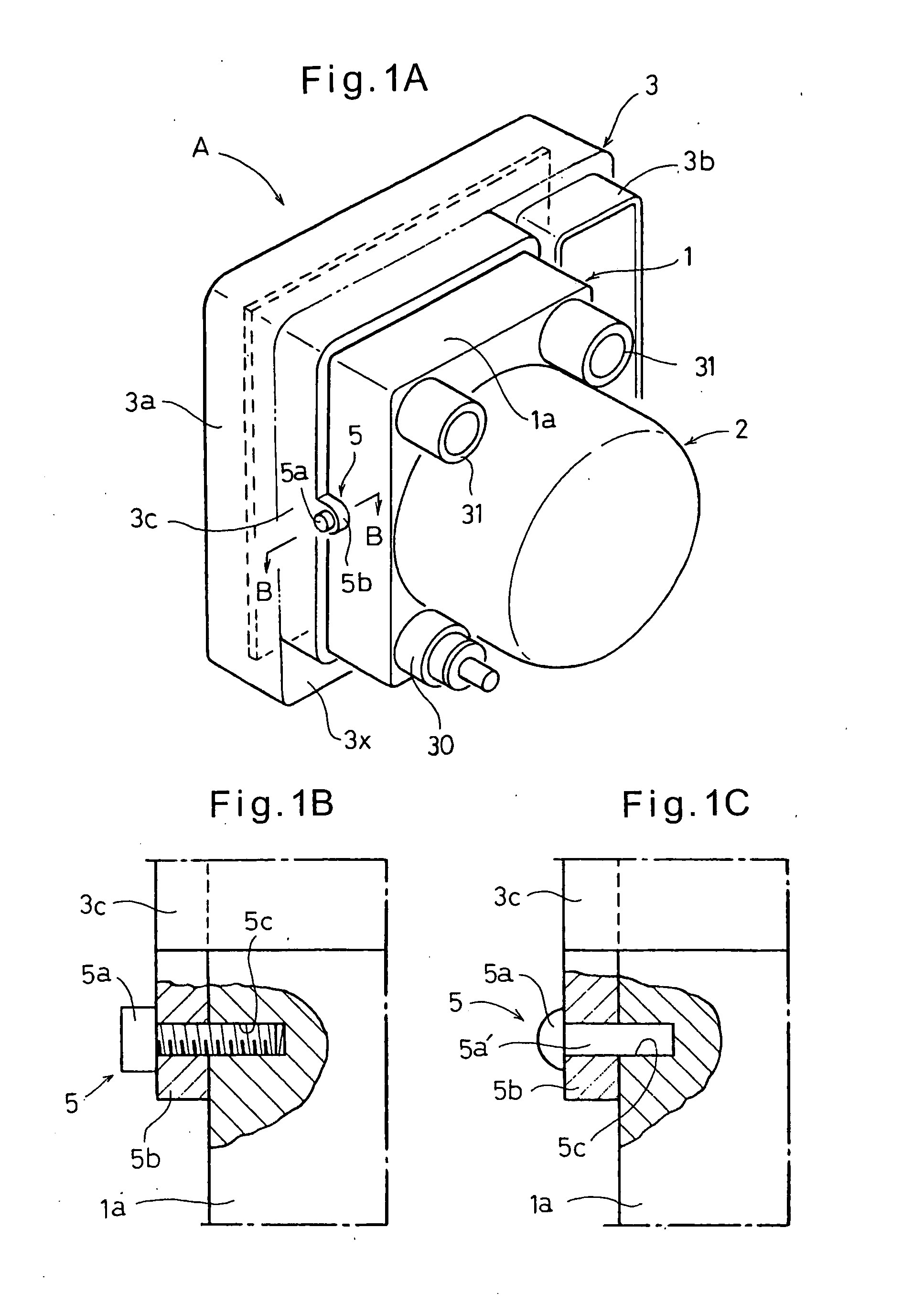
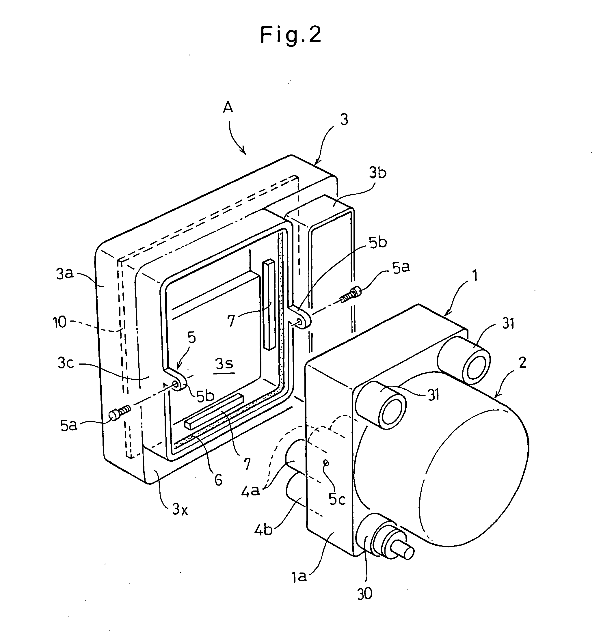
[0034] Now referring to FIGS. 1 and 2, the hydraulic pressure controller A of this embodiment comprises a hydraulic unit 1 including hydraulic pumps, solenoid valves 4a and 4b (FIGS. 2 and 3) and a reservoir, an electric motor 2 for driving the hydraulic pumps, and an electronic control unit 3 for controlling and driving the solenoid valves, the motor and other electric actuators. The electronic control unit 3 has its housing 3a joined to a block 1a of the hydraulic unit 1. The hydraulic pressure controller A shown is an element of an anti-lock brake system (ABS).

[0035] The block 1a is a relatively thick, substantially box-shaped member made of an aluminum alloy and formed with a cavity in which are received the hydraulic pumps (not shown). The pumps, the solenoid valves 4a and 4b, and other elements of the controller A are connected together through flow passages formed in the block la. A conventional such block 1a has a size or volume that is slightly greater than that of the hou...


PUM


Abstract

A hydraulic pressure controller is provided which includes a hydraulic unit for controlling hydraulic pressure and an electronic control unit. The hydraulic unit includes a block in which are mounted electric actuators. The electronic control unit controls the electric actuators by applying electric signals thereto to control hydraulic pressure produced in the hydraulic unit to external elements in a controlled manner, thereby controlling the behavior of the vehicle. The electronic control unit includes a housing in which are mounted a circuit board and other electronic and electric parts, and a fitting portion provided on the housing so as to face one side of the block. The controller further includes a fastener for joining the block to the fitting portion.

Description

BACKGROUND OF THE INVENTION [0001] This invention relates to a compact hydraulic pressure controller for use in e.g. a vehicle brake system, comprising a hydraulic unit and an electronic control unit joined to the hydraulic unit for controlling the hydraulic unit. [0002] Modern motor vehicles are equipped with various hi-tech devices such as an anti-lock brake system (ABS), which obviates imminent lock-up of any vehicle wheel, thereby achieving optimum and efficient braking, a vehicle stability control (VSC) system, which controls brake pressures in individual wheel cylinders to keep a stable state of the vehicle, and a traction control (TRC) system. These devices have an electronic control unit (ECU) for controlling the entire system to adjust hydraulic pressures to the individual wheel cylinders. [0003] The hydraulic unit, which includes solenoid valves and an actuator such as a pump unit, the motor, and the ECU are usually joined together to form a hydraulic pressure controller m...

Claims


Application Information

Patent Timeline
IPC IPC(8): B60T8/1761B60T8/34B60T8/36
CPCY10S303/10B60T8/368Y10T137/87885
Inventor SEGAWA, TAROSHIBATA, TAKAYUKIKONDO, MASUHIRO
Owner ADVICS CO LTD
Why Eureka
Try Eureka