Dielectric antenna and radio device using the same

a radio device and dielectric technology, applied in the field of dielectric antennas, can solve the problems of large and heavy dielectric antennas, difficult operation to evenly fill the inside of the waveguide with dielectrics, and high machining costs of conventional dielectric antennas, and achieve the effect of large primary beam width and high gain

Active Publication Date: 2005-03-17
PANASONIC INTELLECTUAL PROPERTY CORP OF AMERICA
View PDF7 Cites 68 Cited by
  • Summary
  • Abstract
  • Description
  • Claims
  • Application Information

AI Technical Summary

Benefits of technology

Therefore, a first object of the present invention is to provide a dielectric antenna with a high gain and a large primary beam width.

Problems solved by technology

Moreover, the conventional dielectric antenna as illustrated in FIG. 62 uses a metal waveguide including two metal plates attached together as the feed circuit, whereby the dielectric antenna is large and heavy.
Thus, the conventional dielectric antenna requires high machining cost.
However, it requires a difficult operation to evenly fill the inside of the waveguide with a dielectric.
Therefore, the dielectric filling has not been a practical option.

Method used


Image

  • Dielectric antenna and radio device using the same
  • Dielectric antenna and radio device using the same
  • Dielectric antenna and radio device using the same

Examples


first embodiment

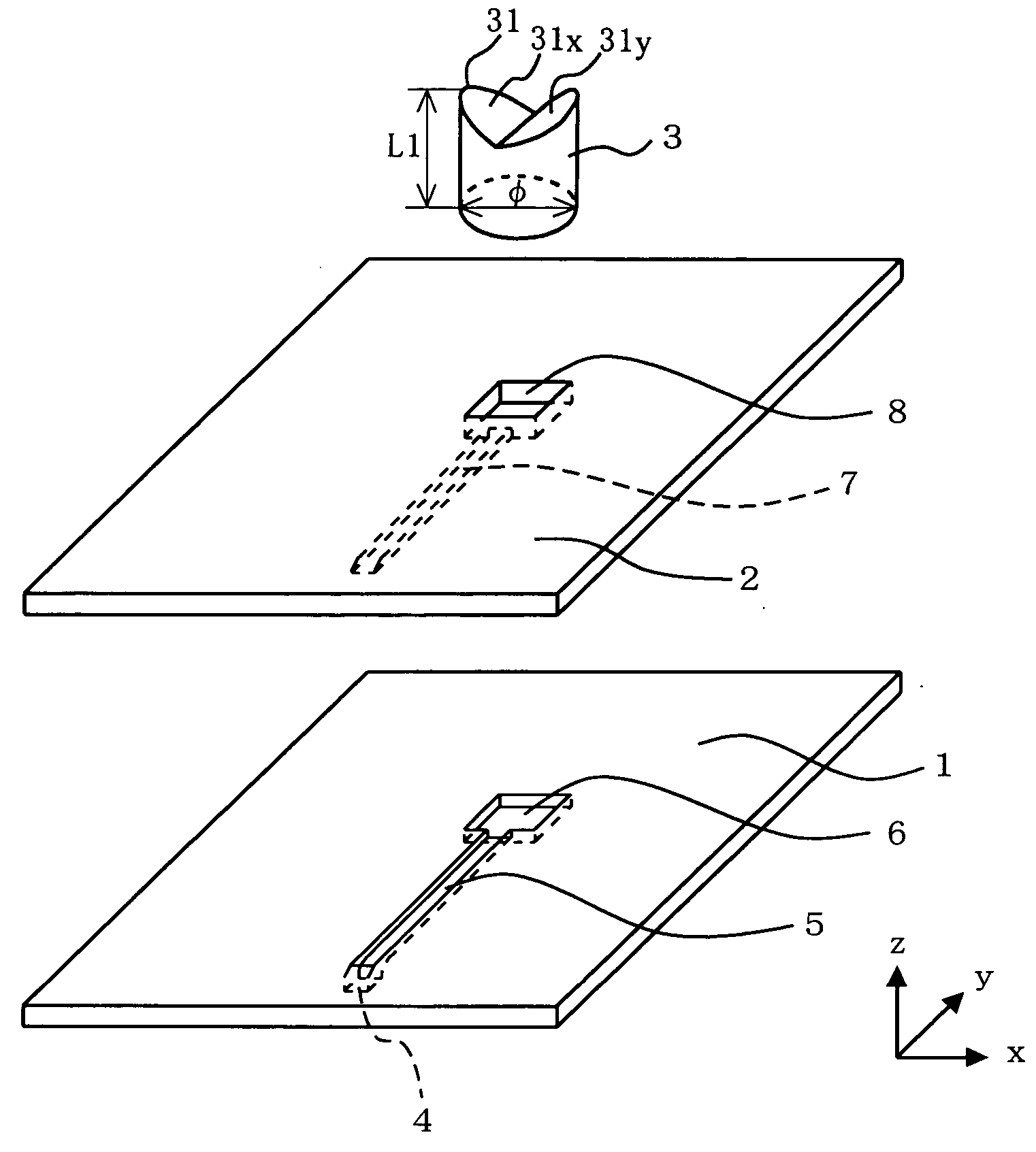
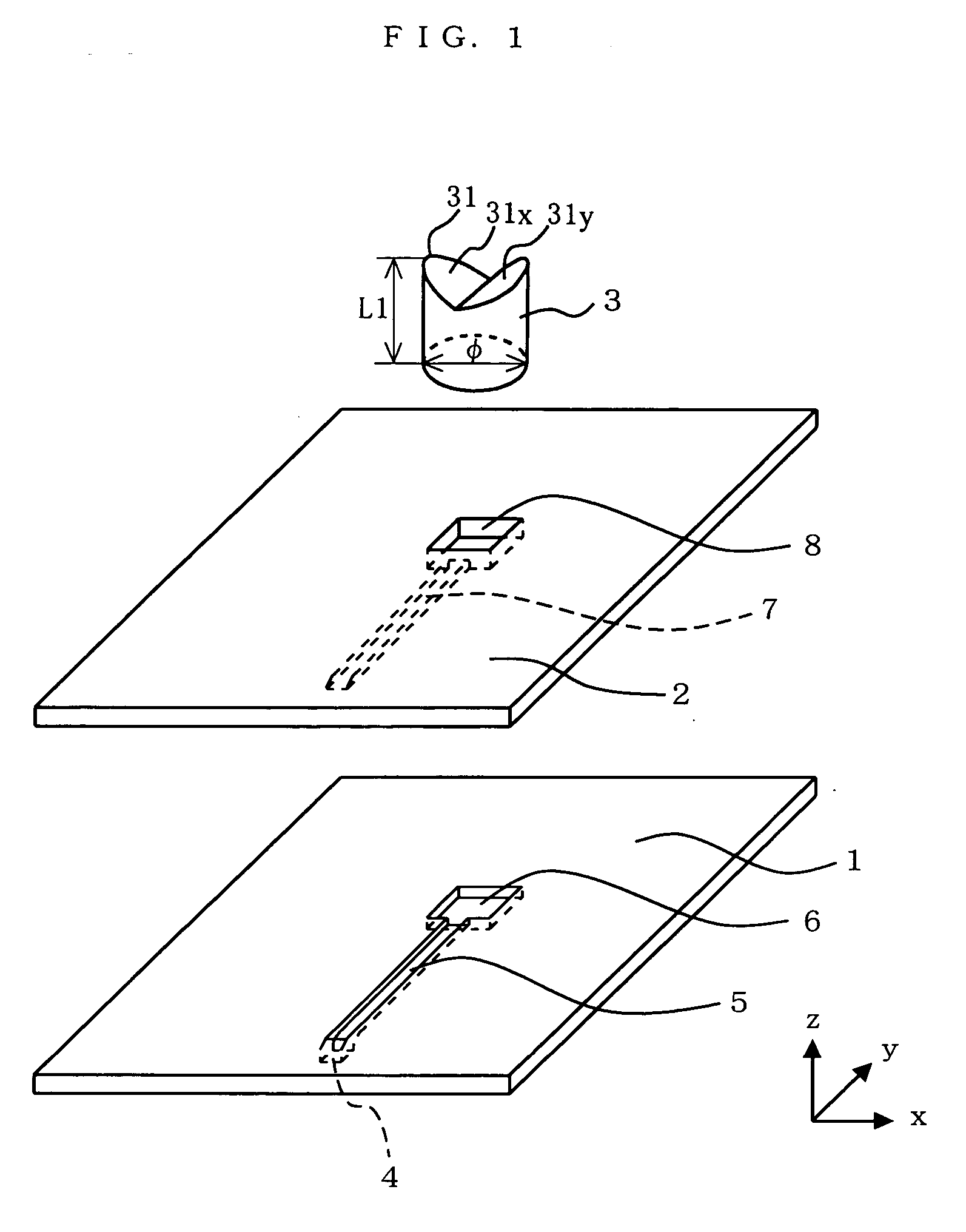
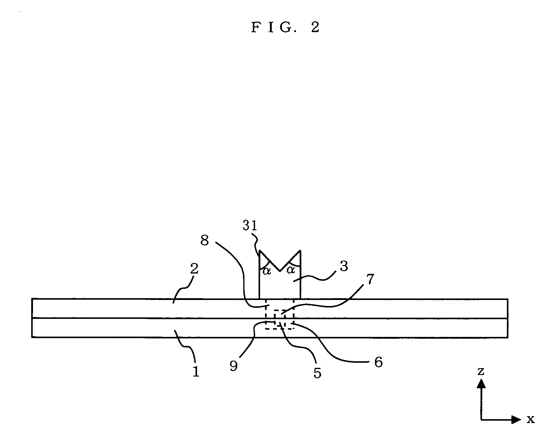
FIG. 1 is an exploded perspective view illustrating a dielectric antenna according to the first embodiment of the present invention. FIG. 2 is a front view of the dielectric antenna illustrated in FIG. 1. In these and subsequent figures, it is assumed that the xz plane represents the electric field plane, and the yz plane represents the magnetic field plane. Referring to FIG. 1 and FIG. 2, the dielectric antenna includes a lower conductor plate 1, an upper conductor plate 2 and a loading dielectric block 3.

The loading dielectric block 3 is made of a dielectric material such as polypropylene. A notch 31 is formed in an upper portion of the loading dielectric block 3. The notch 31 is formed by cutting off an upper portion of a cylindrical dielectric with an edged tool, or the like. The notch 31 is formed by cutting the cylindrical dielectric from two opposite points along the circumference of the upper surface of the cylindrical dielectric in an inclined downward direction at an ang...

second embodiment

The second embodiment of the present invention differs from the first embodiment only in the shape of the loading dielectric block. Otherwise, the dielectric antenna of the second embodiment is as illustrated in FIG. 1. Therefore, only the shape of the loading dielectric will be discussed below. FIG. 9 is a perspective view illustrating a loading dielectric block used in the dielectric antenna according to the second embodiment of the present invention. FIG. 10 is a vertical cross-sectional view of the loading dielectric block of FIG. 9 taken along line A-B.

Referring to FIG. 9 and FIG. 10, a depressed portion 32 is formed in an upper portion of a loading dielectric block 3b. The depressed portion 32 is formed by cutting off an upper portion of a cylindrical dielectric with an edged tool, or the like. The depressed portion 32 is formed by cutting the cylindrical dielectric from two opposite points along the circumference of the upper surface of the cylindrical dielectric in an inc...

third embodiment

FIG. 12 is an exploded perspective view illustrating a dielectric antenna according to the third embodiment of the present invention. In FIG. 12, elements that are functionally the same as those of the first embodiment will be denoted by the same reference numerals and will not be further described below. The third embodiment uses, as the loading dielectric, a loading dielectric block 3d having a depressed portion 34 whose upper portion has a truncated cone shape. The loading dielectric block 3d has the depressed portion 34, whereby the upper portion thereof is in a bowl shape, and the depressed portion 34 includes, at the bottom thereof, a flat (horizontal) surface portion 34a parallel to the bottom surface of the loading dielectric block 3d. FIG. 13 is an enlarged perspective view of the loading dielectric block 3d.

Thus, with the loading dielectric block 3d with the bowl-shaped upper portion, an omni directional slope is formed toward the periphery with a flat bottom portion at ...


PUM


Abstract

A dielectric antenna of the present invention includes a pillar-shaped dielectric section for radiating an electromagnetic wave being fed thereto. The dielectric section includes a depressed portion in an upper portion thereof. The vertical cross section of the depressed portion has such a shape that the height of the dielectric section gradually increases toward the side surface of the dielectric section. For example, the depressed portion is a notch having a V-shaped vertical cross section. Alternatively, the depressed portion includes a flat surface portion.

Description

BACKGROUND OF THE INVENTION 1. Field of the Invention The present invention relates to an antenna for use in the microwave and millimeter-wave range, and more particularly to a dielectric antenna for radiating an electromagnetic wave from a dielectric. 2. Description of the Background Art Dielectric antennas loaded with a dielectric block placed over a feed circuit, which includes a microstrip line, a waveguide, etc., have been widely used in the art for radio communications in the microwave and millimeter-wave range (see Japanese Laid-Open Patent Publication Nos. 2000-209022 and 2000-278030). Such dielectric antennas are called “waveguide-fed dielectric antennas”. FIG. 62 is an exploded perspective view illustrating a conventional waveguide-fed dielectric antenna. Referring to FIG. 62, the conventional dielectric antenna includes a lower conductor plate 101, an upper conductor plate 102 and a loading dielectric block 103 having a cylindrical shape. The lower conductor plate 101...

Claims


Application Information

Patent Timeline
Patent Type & Authority Applications(United States)
IPC IPC(8): H01Q9/04H01Q21/00H01Q21/06
CPCH01Q9/0485H01Q21/061H01Q21/0075
Inventor OHNO, TAKESHIOGAWA, KOICHI
Owner PANASONIC INTELLECTUAL PROPERTY CORP OF AMERICA
Why Eureka
Try Eureka