Optical range finder with directed attention

a laser range finder and directed attention technology, applied in the direction of distance measurement, instruments, surveying and navigation, etc., can solve the problems of affecting the performance affecting the range of motion of the laser range finder, and requiring high production costs

Active Publication Date: 2005-03-17
DEERE & CO
View PDF29 Cites 94 Cited by
  • Summary
  • Abstract
  • Description
  • Claims
  • Application Information

AI Technical Summary

Benefits of technology

[0004] An optical range finder for determining the distance of an object may comprise an optical source of electromagnetic radiation. A focusing optical member focuses the electromagnetic radiation upon a micro-mirror array. A data processor controls the micro-mirror array to direct the focused electromagnetic radiation in a defined direction or a defined radiation pattern. A beam adjuster determines a transmitted beam size (e.g., beam width) of the defined radiation pattern in a spatial region of interest to provide a desired level of resolution for that spatial region. A transmission optical member focuses the defined radiati...

Problems solved by technology

However, the rotating mirror arrangement is costly to manufacture and susceptible to mechanical failure, such as shock or vibration cracking the mirror or misaligning it.
If the laser range finder is exposed to dust or other particulate matter in an agricultural environment, the range of motion of the laser range finder may be impeded and performance may be degraded.
Vibration of the laser...

Method used


Image

  • Optical range finder with directed attention
  • Optical range finder with directed attention
  • Optical range finder with directed attention

Examples


Embodiment Construction

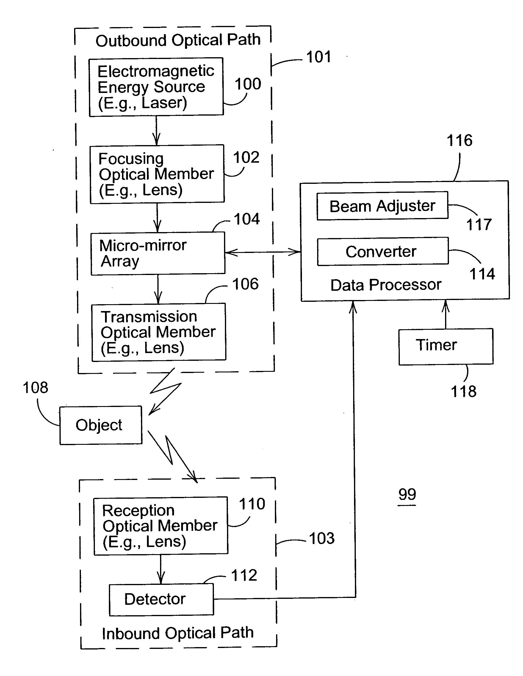
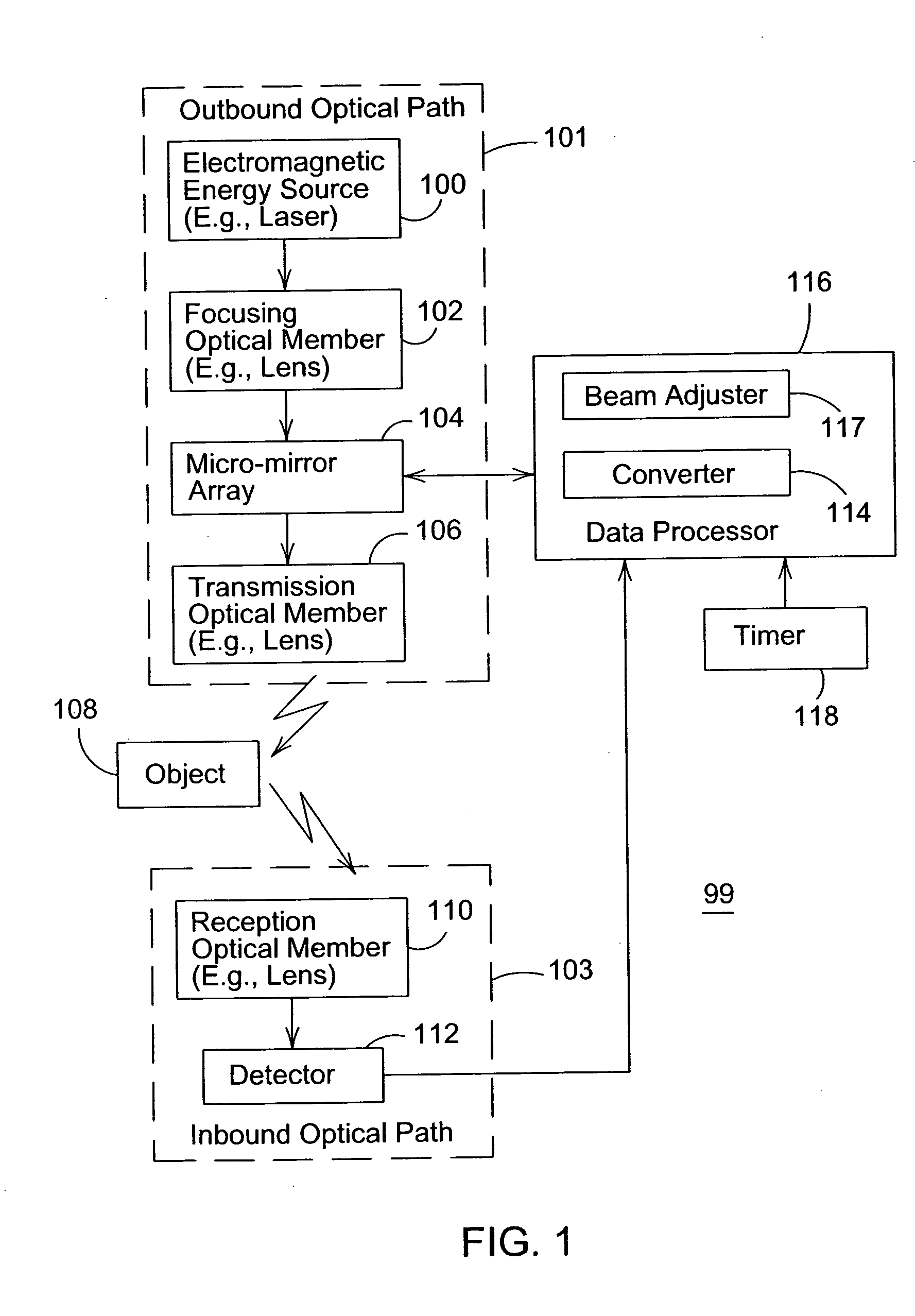
[0012]FIG. 1 shows a block diagram of an optical range finder 99 for determining the distance of an object 108 from a reference point. The reference point may be defined with reference to the range finder 99 or a portion thereof. The optical range finder 99 comprises an outbound optical path 101 and an inbound optical path 103. The outbound optical path 101 is associated with an electromagnetic signal (e.g., a pulse or pulse train) transmitted from the range finder 99 toward an object 108, whereas the inbound optical path 103 is associated with the reflected electromagnetic signal received by the range finder 99. The outbound optical path 101 comprises an electromagnetic energy source 100, a focusing optical member 102, a micro-mirror array 104, and a transmission optical member 106. The inbound optical path 103 comprises a reception optical member 110 and a detector 112.

[0013] The optical range finder 99 comprises an electromagnetic energy source 100 (e.g., a laser) that emits ele...


PUM


Abstract

An optical range finder for determining the distance comprises a focusing optical member that focuses emitted electromagnetic radiation upon a micro-mirror array. A processor controls the micro-mirror array to direct the focused electromagnetic radiation into a defined radiation pattern consistent with a lower resolution scan over a greater area and a higher resolution scan over a lesser area of interest within the greater area. A transmission optical member focuses the defined radiation pattern toward an object. A reception optical member receives electromagnetic radiation reflected from the object. A detector detects the receipt of the reflected electromagnetic radiation. A timer determines an elapsed time, between transmission of the electromagnetic radiation to the object and receipt of the electromagnetic radiation from the object, to facilitate determination of the distance between the object and the range finder.

Description

FIELD OF THE INVENTION [0001] This invention relates to an optical range finder with directed attention. BACKGROUND OF THE INVENTION [0002] A range finder means an instrument or device used to determine the distance of an object from a reference point. In the prior art, a laser range finder may use a rotating mirror assembly to direct a beam transmitted from the laser range finder. A laser measurement system of the prior art may include a mechanically operated mirror, which scans through a certain requisite range of motion to reach a desired setting or angular position. Because such mechanical scanners must typically scan through a certain range of motion to reach a desired steering of a laser or light beam, the practical response time of the mechanical laser scanner is greater than desired for certain applications, such as vehicular control. To improve the scan rate of the mechanical scanner, a laser source may be reflected from a multi-sided rotating mirror or prism to produce a b...

Claims


Application Information

Patent Timeline
IPC IPC(8): G01S7/481G01S17/10G01S17/42G01S17/86G01S17/89
CPCG01S7/4814G01S7/4817G01S17/89G01S17/10G01S17/42G01S17/023G01S17/86
Inventor ANDERSON, NOEL WAYNETHACKRAY, ROBERT GEORGE
Owner DEERE & CO
Why Eureka
Try Eureka