Information transmission system

a technology of information transmission system and information transmission, applied in the field of information transmission system, can solve the problems of reducing the error correction capability of the des, affecting the accuracy of the information transmitted, and the calculation of authentication or certification taking a relatively long tim

Active Publication Date: 2005-03-17
RAKUTEN GRP INC
View PDF9 Cites 14 Cited by
  • Summary
  • Abstract
  • Description
  • Claims
  • Application Information

AI Technical Summary

Benefits of technology

[0031] According to this invention, a composite signal received by a receiving apparatus has a data area interval occurring synchronously with a first sync signal and containing encryption-resultant information. The data area interval follows a prescribed time interval synchronous with the first sync signal. The receiving apparatus has a portion for generating a pseudo random number signal by implementing a shifting action. This portion is also designed for detecting a total number of times a detected second sync signal occurs during the data area interval, for subtracting the detected total number from a predetermined number to get a subtraction result, and for implementing the shifting action a number of times equal to the subtraction result during the next prescribed time interval. Thus, the number of times the shifting action is implemented can be corrected to a normal value which occurs in the absence of a failure to detect a second sync signal or signals in the data area interval. Therefore, it is possible to compensate for a failure to detect a second sync signal or signals in the data area interval which would break encryption / decryption-related synchronization between a sending apparatus and the receiving apparatus.

Problems solved by technology

Thus, the DES tends to decrease the error correction capability.
The calculations for the authentication or the certification take a relatively long time.

Method used


Image

  • Information transmission system
  • Information transmission system
  • Information transmission system

Examples


first embodiment

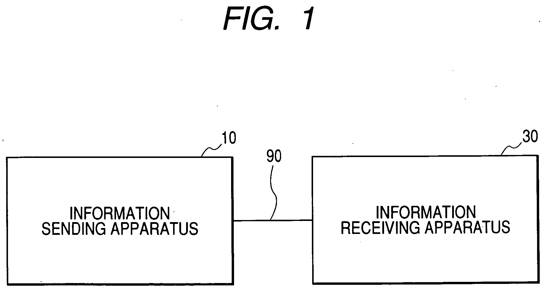
[0041]FIG. 1 shows an information transmission system according to a first embodiment of this invention. The information transmission system of FIG. 1 includes an information sending apparatus 10 and an information receiving apparatus 30 which are bidirectionally connected via a transmission line 90. The transmission line 90 may contain a communication network or a spatial transmission medium.

[0042] The information sending apparatus 10 outputs an information signal to the transmission line 90. The information signal propagates along the transmission line 90 before reaching the information receiving apparatus 30. The information receiving apparatus 30 receives the information signal from the transmission line 90.

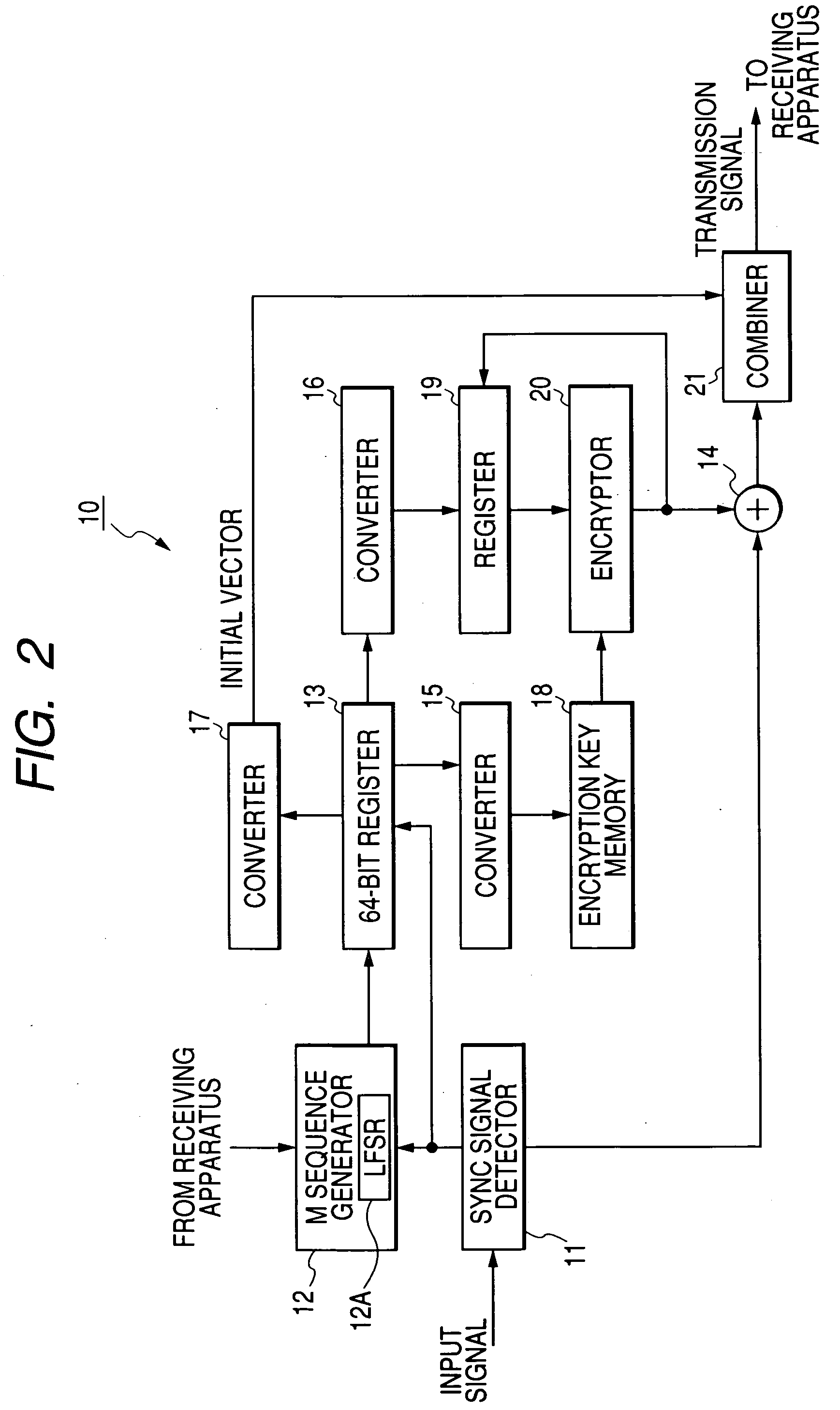
[0043] As shown in FIG. 2, the information sending apparatus 10 includes a sync signal detector 11, a maximum length sequence generator (an M sequence generator) 12, a 64-bit register 13, an adder (a modulo-2 adder) 14, converters 15, 16, and 17, a memory 18, a register 19,...

second embodiment

[0080]FIG. 5 shows an information sending apparatus 10A in a second embodiment of this invention. The information sending apparatus 10A is similar to the information sending apparatus 10 (see FIG. 2) except for design changes mentioned hereafter.

[0081] As shown in FIG. 5, the information sending apparatus 10A includes a sync signal detector 11A, memories 18A and 18B, and a selector 18C. The sync signal detector 11A replaces the sync signal detector 11 in FIG. 2. The memories 18A and 18B are connected with the sync signal detector 11A, a converter 15, and the selector 18C. The selector 18C is connected with the sync signal detector 11A and an encryptor 20. The combination of the memories 18A and 18B, and the selector 18C replaces the memory 18 in FIG. 2.

[0082] An input signal fed to the sync signal detector 11A includes horizontal sync signals of two different types “A” and “B”, that is, horizontal sync signals “A” and horizontal sync signals “B”. The horizontal sync signals “A” di...

third embodiment

[0102] A third embodiment of this invention is similar to the second embodiment thereof except for design changes mentioned hereafter.

[0103]FIG. 8 shows an information sending apparatus 10B in the third embodiment of this invention. The information sending apparatus 10B is similar to the information sending apparatus 10A (see FIG. 5) except that a preprocessor 95 is provided. As shown in FIG. 8, the preprocessor 95 is connected with a sync signal detector 11A.

[0104] The preprocessor 95 receives an input signal including horizontal sync signals, vertical sync signals, blanking signals, and stream data such as video data. Horizontal sync signals in the input signal are of only one type. The preprocessor 95 converts the input signal into a preprocessed signal including horizontal sync signals of two different types “A” and “B”. The preprocessor 95 outputs the preprocessed signal to the sync signal detector 11A.

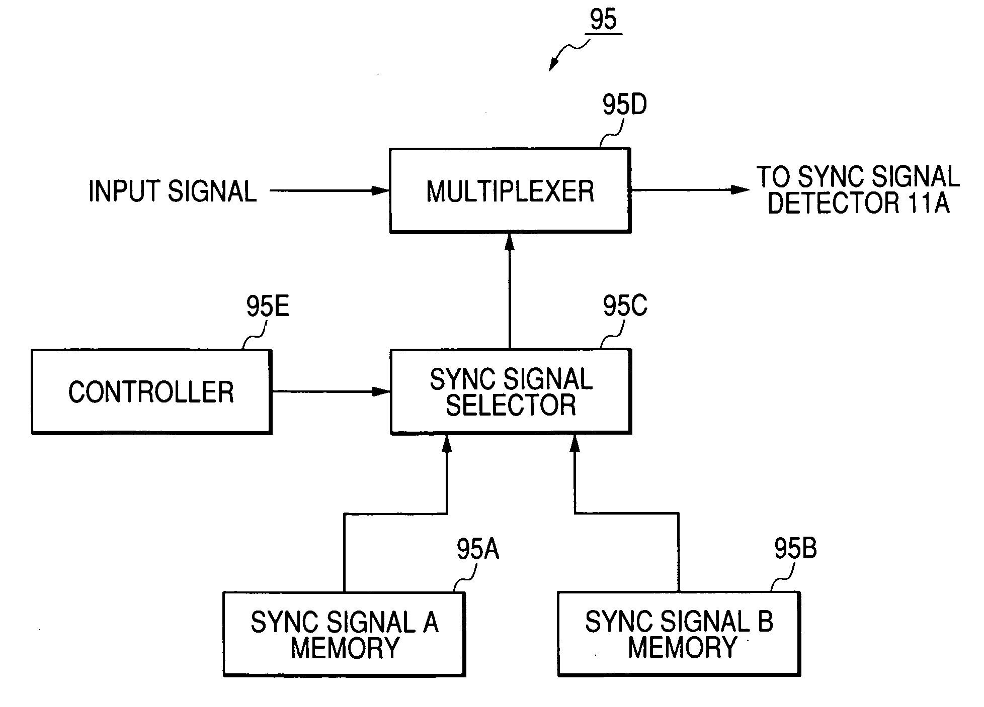
[0105] As shown in FIG. 9, the preprocessor 95 includes memories 95A and ...


PUM


Abstract

A sending apparatus generates a first initial vector, a second initial vector, and an encryption key in response to a pseudo random number. Original information is encrypted into cipher information in response to the encryption key and the second initial vector. The cipher information and the first initial vector are transmitted from the sending apparatus to a receiving apparatus. The receiving apparatus generates a first initial vector, a second initial vector, and an encryption key in response to a pseudo random number equal to that in the sending apparatus. The cipher information is decrypted back to the original information in response to the generated encryption key and the generated second initial vector. The receiving apparatus compares the received first initial vector and the generated first initial vector to check whether or not encryption/decryption-related synchronization between the sending apparatus and the receiving apparatus is normally maintained.

Description

BACKGROUND OF THE INVENTION [0001] 1. Field of the Invention [0002] This invention generally relates to an information transmission system. This invention particularly relates to a system for transmitting digital information while keeping it secret. In addition, this invention relates to a method of transmitting cipher information. [0003] 2. Description of the Related Art [0004] In a conventional digital-information transmission system, digital data (digital information) to be transmitted is processed into a prescribed transmission format before being actually transmitted. Specifically, the digital data is divided into equal-size segments. A sync signal is added to the head of every data segment while a parity signal is added to the end thereof. The sync signal is designed for the identification of the first bit in the data segment. The parity signal is designed for the detection of an error or errors in the data segment. A set of the sync signal, the data segment, and the parity si...

Claims


Application Information

Patent Timeline
Patent Type & Authority Applications(United States)
IPC IPC(8): H04K1/00H04L9/00H04L9/12H04L9/22H04N7/16H04N7/24
CPCH04L9/12H04L9/0891H04L9/0662
Inventor HIGURASHI, SEIJI
Owner RAKUTEN GRP INC
Why Eureka
Try Eureka