Image transformation method and apparatus, image recognition apparatus, robot control apparatus and image projection apparatus

Inactive Publication Date: 2005-03-17
FUJITSU LTD
View PDF13 Cites 8 Cited by
  • Summary
  • Abstract
  • Description
  • Claims
  • Application Information

AI Technical Summary

Benefits of technology

Accordingly, it is a general object of the present invention to provide a novel and useful image transformation method and apparatus, im

Problems solved by technology

However, as the movements of the robot hand become complex, the camera cannot always pickup the image in a direction perpendicular to the substrate surface.
In such a case, it is difficult to accurately detect various shapes within the image and the position of the robot hand above the substrate surface, based on the image which is picked up from the direction tilted with respect to the substrate surface.
But depending on the number and size of the parts to be mounted on the substrate, there is a limit to the number of marks that may be provided on the substrate, and further, the marks may become hidden by the mounted parts.
If the shape detection accuracy with respect to the various shapes within the picked up image is poor, the image recognition accuracy using the picked up image deteriorates.
In addition, when the shape detection accuracy with respect to the various shapes within the picked up image and the position detection accuracy with respect to the robot hand are poor, the mounting position accuracy of the

Method used


Image

  • Image transformation method and apparatus, image recognition apparatus, robot control apparatus and image projection apparatus
  • Image transformation method and apparatus, image recognition apparatus, robot control apparatus and image projection apparatus
  • Image transformation method and apparatus, image recognition apparatus, robot control apparatus and image projection apparatus

Examples


Example

A description will be given of embodiments of the image transformation method and apparatus, the image recognition apparatus, the robot control apparatus and the image projection apparatus according to the present invention, by referring to the drawings.

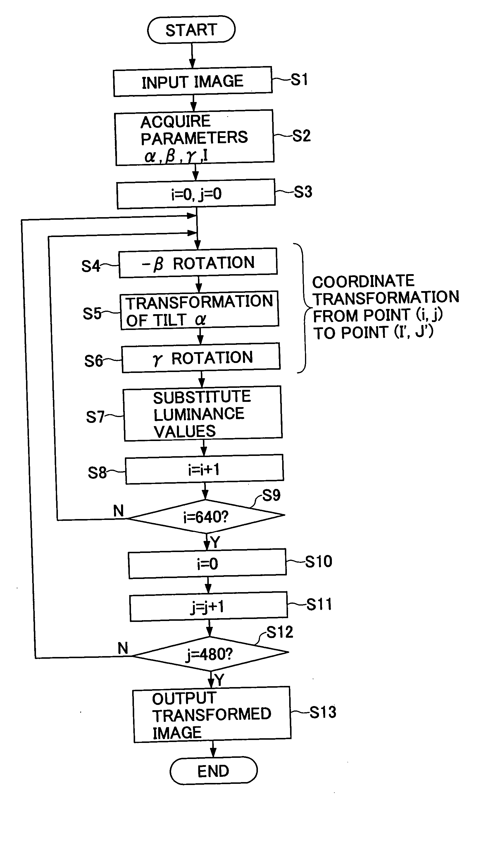
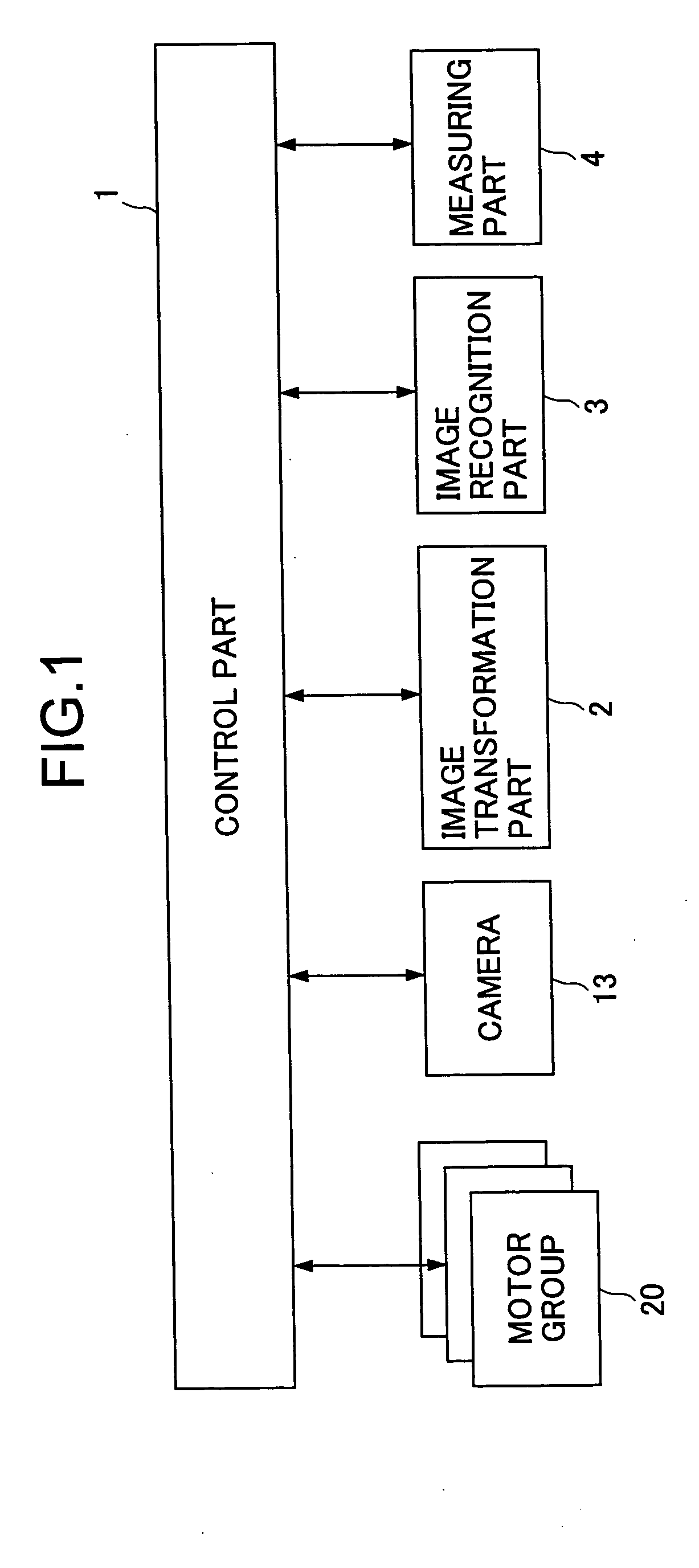
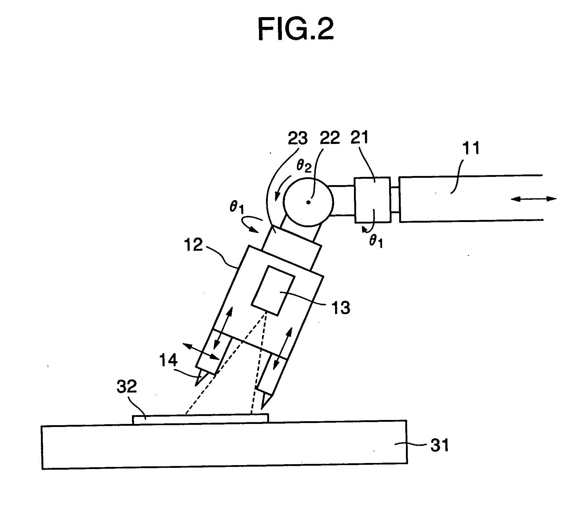
FIG. 1 is a system block diagram showing an embodiment of the robot control apparatus according to the present invention. This embodiment of the robot control apparatus employs an embodiment of the image transformation method according to the present invention, an embodiment of the image transformation apparatus according to the present invention, and an embodiment of the image recognition apparatus according to the present invention.

The robot control apparatus shown in FIG. 1 includes a control part 1, an image transformation part 2, an image recognition part 3 and a measuring part 4. A camera 13 and a motor group 20 are provided in a robot which will be described later in conjunction with FIG. 2. The control part 1 has a known ...


PUM


Abstract

An image transformation method to be implemented by a computer carries out an image transformation process, by transforming a picked up image that is picked up by a pickup unit having an optical axis tilted by an arbitrary angle with respect to a reference plane into an image substantially equivalent to a picked up image that is picked up by the pickup unit in a state where the optical axis of the pickup unit is perpendicular to the reference plane, and substituting luminance values of coordinates before the transformation as luminance values corresponding to coordinate values after the transformation.

Description

BACKGROUND OF THE INVENTION 1. Field of the Invention The present invention generally relates to image transformation methods and apparatuses, image recognition apparatuses, robot control apparatus and image projection apparatuses, and more particularly to image transformation method and apparatus for obtaining position coordinates by transforming image information picked up (or imaged) by an image pickup device (or imaging device), an image recognition apparatus for recognizing an image based on the position coordinates obtained by such an image transformation method, a robot control apparatus which uses such an image recognition apparatus, and an image projection apparatus which uses such an image transformation method. 2. Description of the Related Art When assembling parts, devices and the like using a robot, it is necessary to accurately control movements of each part of an arm, a hand and the like of the robot. For example, when mounting a part on a substrate, the position...

Claims


Application Information

Patent Timeline
IPC IPC(8): G06T3/00G06T5/00H04N5/74
CPCG06T3/00H04N5/74G06T5/006
Inventor FUJIMOTO, TAKAYUKI
Owner FUJITSU LTD
Why Eureka
Try Eureka