
Tunable dispersion compensator

Active Publication Date: 2005-03-17
ALCATEL-LUCENT USA INC +1
View PDF7 Cites 31 Cited by
  • Summary
  • Abstract
  • Description
  • Claims
  • Application Information

AI Technical Summary

Benefits of technology

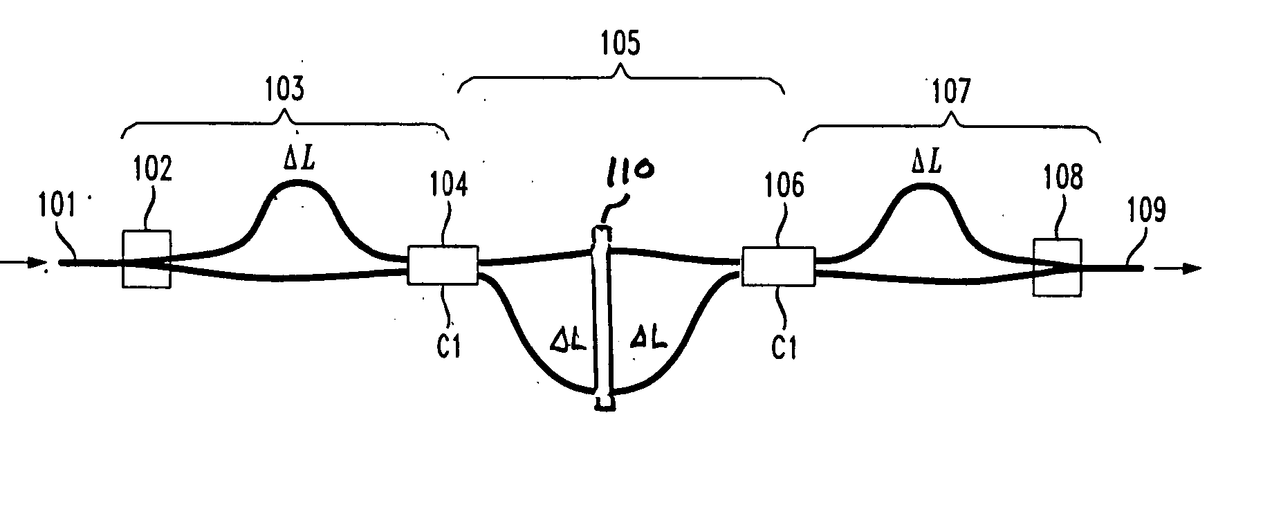
[0007] In accordance with the present invention, I disclose a method and apparatus for implementing a colorless polarization independent Mach-Zehnder-interferometer (MZI)-based tunable dispersion compensator (TDC) that has only three MZI stages (two in a reflective version) and two adjustable couplers which are responsive to one control voltage, making it compact, low power, and simple to fabricate, test, and operate. Polarization independence is achieved using a half-wave plate positioned across the midpoints of the two path lengths of middle stage MZI to exchange the TE and TM polarizations. Such an MZI-based TDC with a 25-GHz-free-spectral-range version can compensate˜±2100 ps / nm for 10 Gb / s signals. Having a free-spectral range equal to the system channel spacing divided by an integer makes it possible for the TDC to compensate many channels either simultaneously and also compensate the case where the wavelength is jumping between different channels without adjustment of the TDC. For example, the 25 GHz free-spectral range, as well as the free-spectral ranges 20 GHz and 33.3 GHz, will allow for the TDC to compensate multiple channels on a 100-GHz grid
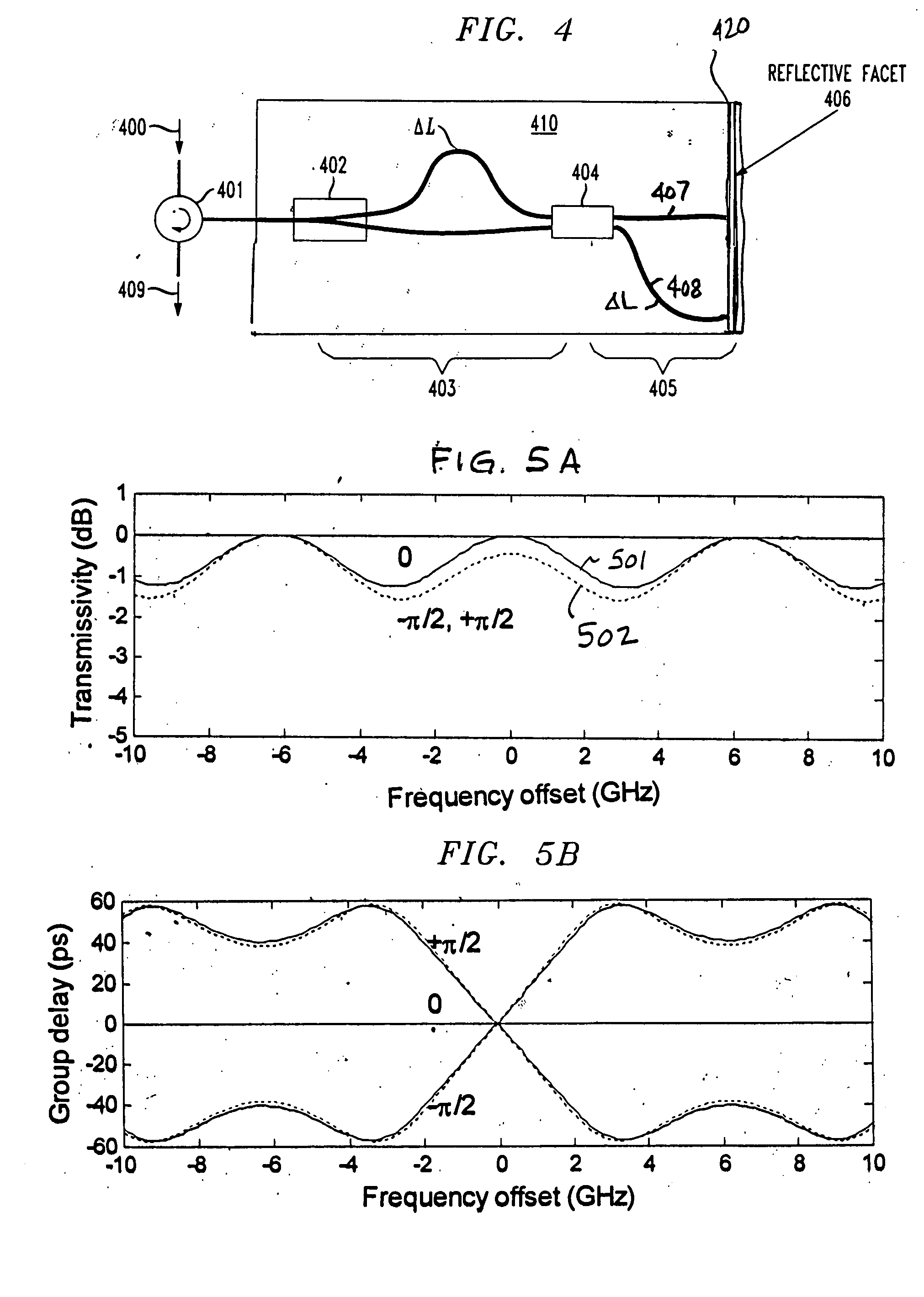
[0016] In yet another embodiment, a double-pass MZI-TDC arrangement is formed by placing a reflector after the TDC such that the signal passes through the TDC twice. This double-pass increases the amount of achievable dispersion. If polarization independence is desired, a quarter-wave plate can be placed between the TDC and the reflector.

Problems solved by technology

This large number of stages and control voltages is expensive and power-consuming to fabricate and operate, especially when compensating 10 Gb / s signals.
Because fabrication accuracy cannot guarantee the relative phases of such long path-length differences, every stage of every device must be individually characterized.
Also, a large number of stages often results in a high optical loss and a large form factor.
Additionally, the more the stages, the more difficult it is to achieve polarization independence.

Method used


Image

  • Tunable dispersion compensator
  • Tunable dispersion compensator
  • Tunable dispersion compensator

Examples


Embodiment Construction

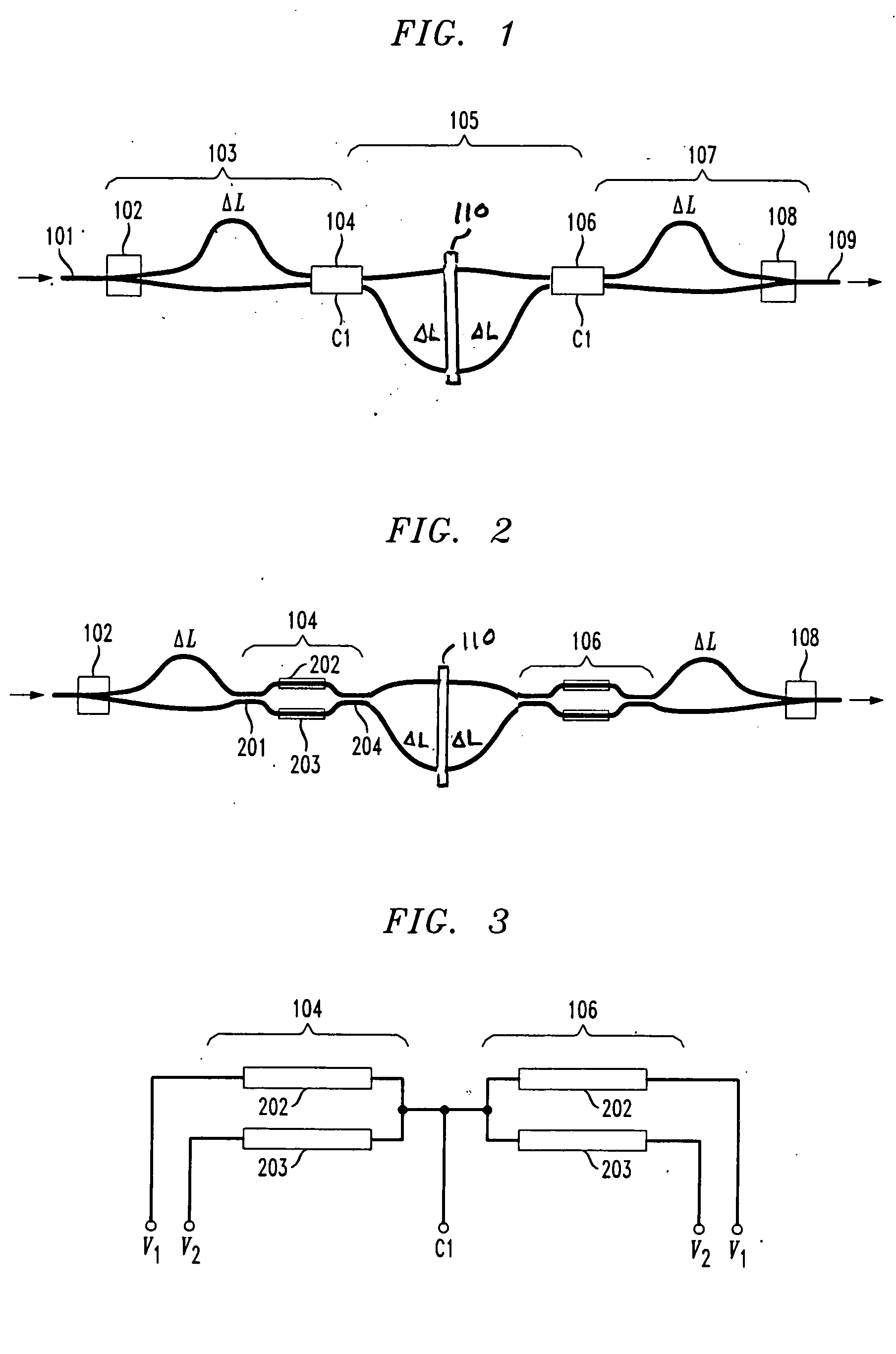
[0029] With reference to FIG. 1 there is shown, in accordance with the present invention, an illustrative diagram of my polarization independent tunable dispersion compensator (TDC) device that has only three stages and uses one control voltage. The three stages 103, 105, and 107 are implemented using Mach-Zehnder-interferometers (MZIs). The first and second MZIs 103, 105 share an adjustable coupler 104 and the second and third MZIs 105, 107 share an adjustable coupler 106. The two adjustable couplers 104, 106 are always set equally. The first and third MZI have path-length differences ΔL, and the center MZI has a path-length difference of 2ΔL (plus any phase offset from the couplers). Note that in the preferred embodiment shown in FIG. 1, the longer path-length is located in the top, bottom, and top arms of the first, second and third MZIs, 103, 105, 107, respectively. This allows the structure to be folded into a compact arrangement as shown in the waveguide layout of FIG. 10. Alt...


PUM


Abstract

A method and apparatus for implementing a colorless polarization independent Mach-Zehnder-interferometer (MZI)-based tunable dispersion compensator (TDC) that has only three MZI stages (two in a reflective MZI-TDC ) and two adjustable couplers which are responsive to one control voltage, making it compact, low power, and simple to fabricate, test, and operate. Polarization independence is obtained by using a half-wave plate positioned across the midpoints of the two path lengths of middle stage MZI of the three stage MZI-TDC and by using a quarter-wave plate in front of a reflective facet of the reflective MZI-TDC. A cascaded MZI-TDC arrangement with also only a single control is formed by cascading two MZI-TDC arrangements and driving all adjustable couplers with the same control signal.

Description

REFERENCE TO PARENT APPLICATION [0001] This is a continuation-in-part of co-pending patent application identified as C. R. Doerr 79, Ser. No. 10 / 664,340, filed Sep. 17, 2003.TECHNICAL FIELD OF THE INVENTION [0002] This invention relates generally to optical dispersion compensators and, more particularly, to a method and apparatus for implementing a colorless Mach-Zehnder-interferometer-based tunable dispersion compensator. BACKGROUND OF THE INVENTION [0003] Optical signal dispersion compensators can correct for chromatic dispersion in optical fiber and are especially useful for bit rates 10 Gb / s and higher. Furthermore, it is advantageous for the dispersion compensator to have an adjustable amount of dispersion, facilitating system installation. It is also advantageous if the tunable dispersion compensator (TDC) is colorless, i.e., one device can compensate many channels simultaneously or be selectable to compensate any channel in the system. [0004] Previously proposed colorless TDC...

Claims


Application Information

Patent Timeline
IPC IPC(8): G02B6/34G02F1/01G02B6/12G02F1/225H04B10/18
CPCG02B6/12007G02B6/29355G02B6/2938G02B6/29394H04B10/25133G02B6/29398G02F1/225G02F2201/16G02B6/29395
Inventor DOERR, CHRISTOPHER RICHARD
Owner ALCATEL-LUCENT USA INC
Learn More