Method and device for polishing the surface of a gas turbine blade

a technology of gas turbine blades and surfaces, which is applied in the direction of metal-working equipment, manufacturing tools, abrasion equipment, etc., can solve the problems of unacceptably reducing the surface quality, affecting the quality of the surface,

Inactive Publication Date: 2005-03-17
BUBLATH BORIS +5
View PDF11 Cites 8 Cited by
  • Summary
  • Abstract
  • Description
  • Claims
  • Application Information

AI Technical Summary

Benefits of technology

[0027] The invention also provides an apparatus for removing ceramic material of a ceramic thermal barrier coating on the surface of a gas turbine blade or vane, having a holder for the gas turbine blade or vane and having a nozzle for emitting a dry ice jet, and having a multi-axis manipulation device for moving the dry ice jet relative to the gas turbine blade or vane in such a manner that completely automated removal of the ceramic material of the gas turbine blade or vane becomes possible.
[0028] It is preferable for the dry ice jet also to

Problems solved by technology

Consequently, it has a relatively high roughness, which is undesirable.
The grinding process is not only time-consuming but also entails the risk of prior uncontrolled removal of material at exposed edges.
The known sand-blasting processes in particular have the drawback that solid particles of the j

Method used


Image

  • Method and device for polishing the surface of a gas turbine blade
  • Method and device for polishing the surface of a gas turbine blade
  • Method and device for polishing the surface of a gas turbine blade

Examples


Embodiment Construction

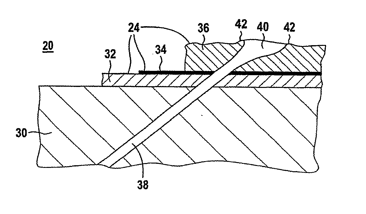
[0033] Identical reference numerals have the same meaning throughout the figures.

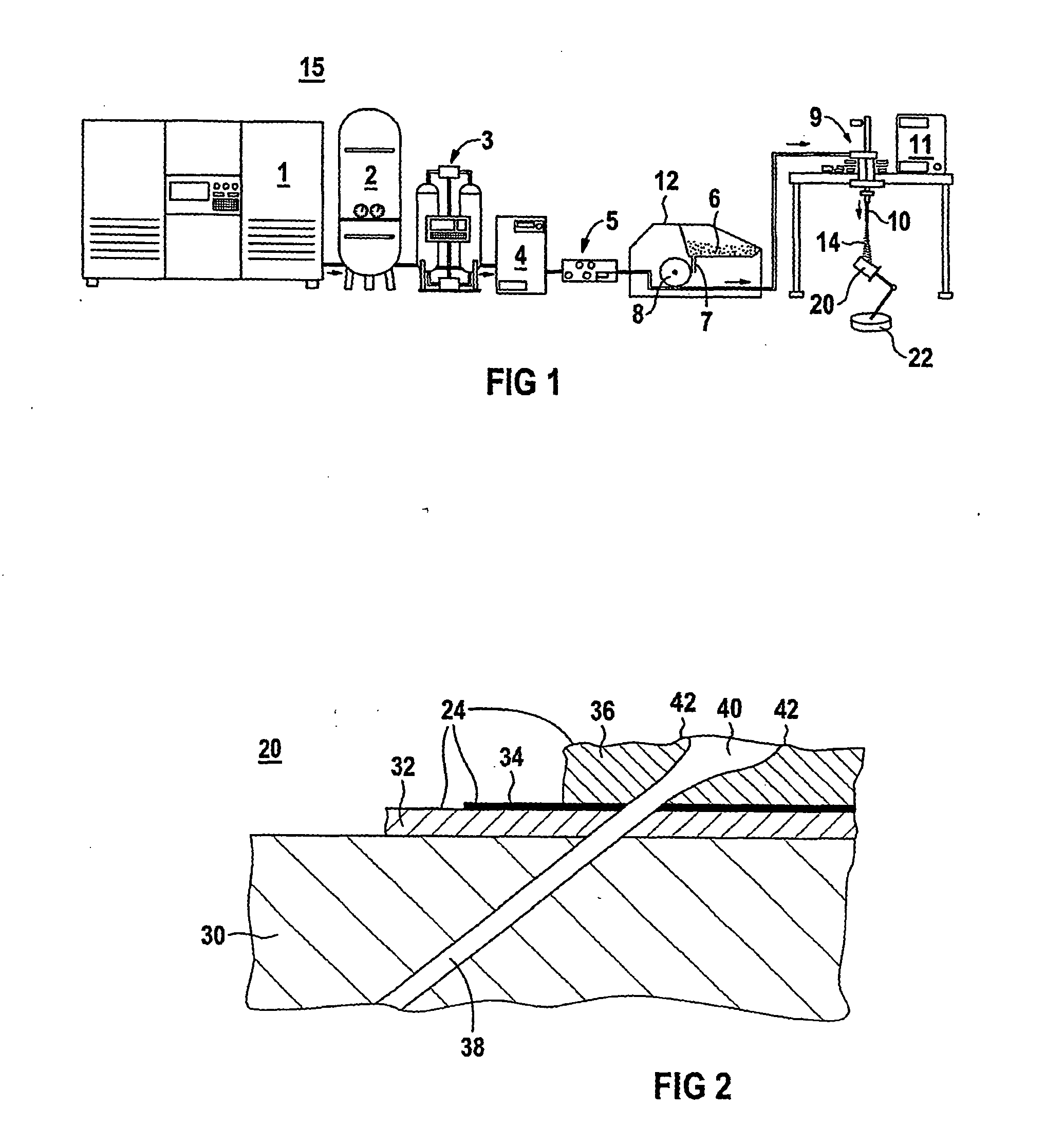
[0034]FIG. 1 shows an apparatus 15 for removing ceramic material from the surface of a gas turbine blade or vane 20. To produce a compressed-air flow, a screw compressor 1, a compensation vessel 2, an adsorption dryer 3, a cooler 4 and a measurement system 5 are connected in series. Air is highly compressed, in particular to a pressure of from 3 to 12 bar, in the screw compressor 1. The compensation vessel 2 is used to stabilize a constant mass flow. In the adsorption dryer 3, the air is dried, and then cooled in the cooler 4. A measurement system 5 is used to record the compressed-air parameters.

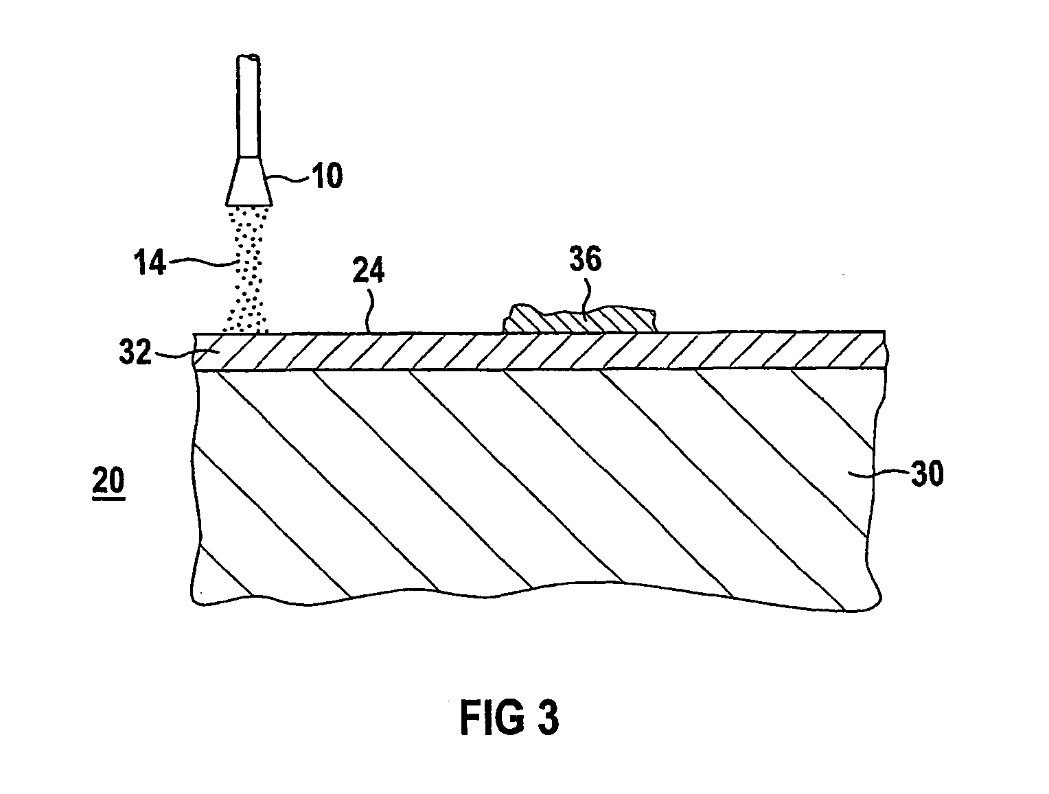
[0035] The compressed-air stream is then fed to a pellet supply device 12, in which dry ice pellets 6 are stored. The dry ice pellets 6 are fed to the compressed-air stream by means of a screw conveyor 7 via a star feeder 8 and are fed with the compressed-air stream to a Laval nozzle 10 which can be moved by ...


PUM

PropertyMeasurementUnit
Pressureaaaaaaaaaa
Pressureaaaaaaaaaa
Pressureaaaaaaaaaa

Abstract

The invention relates to a method and device for polishing the surface of a gas turbine blade. According to the invention, a metallic anticorrosive layer is polished by using a stream of dry ice whereby preventing the surface from becoming contaminated and obtaining cost advantages.

Description

CROSS REFERENCE TO RELATED APPLICATIONS [0001] This application is the US National Stage of International Application No. PCT / EP02 / 12520, filed Nov. 8, 2002 and claims the benefit thereof. The International Application claims the benefits of German application No. 01128915.4 EP filed Dec. 5, 2001, both of the applications are incorporated by reference herein in their entirety.FIELD OF THE INVENTION [0002] The invention is in the field of gas turbine blades or vanes and involves the application or refurbishment of a protective layer or protective layer system on gas turbine blades or vanes. BACKGROUND OF THE INVENTION [0003] Protective layer systems on gas turbine blades or vanes are shown, for example, in U.S. Pat. No. 4,321,310, U.S. Pat. No. 4,676,994 or U.S. Pat. No. 5,238,752. Gas turbine blades and vanes are exposed to very high temperatures. To enable them to have the required resistance to high temperatures, therefore, they are made from materials which are able to withstand ...

Claims


Application Information

Patent Timeline
IPC IPC(8): B23P6/00B24C1/00B24C1/08
CPCB23P2700/06B24C1/003B24C1/086B24C1/083B24C1/08
Inventor BUBLATH, BORISELBING, FELIXKRIEG, MARKREICH, GERHARDREICHE, RALPHSETTEGAST, SILKE
Owner BUBLATH BORIS
Why Eureka
Try Eureka