
System and method for multi-path simulation

a multi-path simulation and simulation system technology, applied in the field of multi-path simulation, can solve the problems of phase shifting of signals, deep fades on signals, and interference by destructive or constructive signals, and achieve the effect of simulating signal attenuation during transmission and reducing the strength of reflected signals

Inactive Publication Date: 2005-03-17
ACCTON TECHNOLOGY CORPORATION
View PDF12 Cites 115 Cited by
  • Summary
  • Abstract
  • Description
  • Claims
  • Application Information

AI Technical Summary

Benefits of technology

[0008] The present invention employs a shielded anechoic chamber to avoid external electromagnetic interference and other uncontrollable transmission paths during testing. The internal walls of the chamber are composed of particular material for absorbing most energy of the signal penetrating the internal walls and reducing the strength of the reflected signal significantly. A reflector within the chamber can be used to simulate the main indirect transmission path. The present invention also employs an attenuating device to attenuate transmitted signals, thereby simulating the signal attenuation during transmission. Thus, the real electromagnetic environment can be simulated without limits of the chamber size, and various radio experiments and measurements may be performed within the simulated environment to obtain reliable results.

Problems solved by technology

The phenomenon results in the constructive or destructive interference, and phase shifting of the signal, caused by the refraction, and the reflection from objects, such as buildings and obstacles.
Especially, the destructive interference resulted from the superposition of the phase of different paths may cause deep fades on signals.
The phenomenon exists in most real environments and would increase the complexity and instability of signal
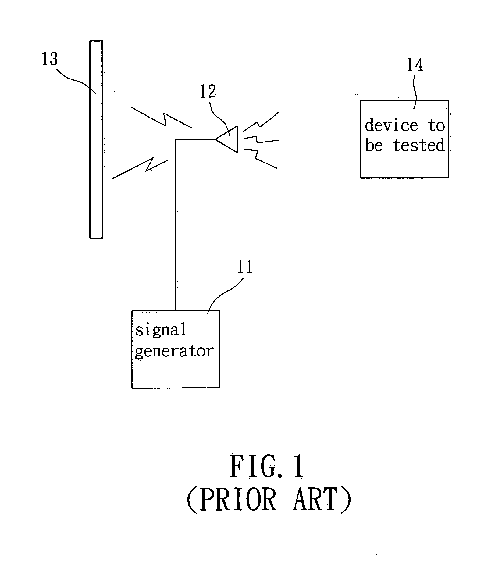
However, there are two major drawbacks in the architecture of FIG. 1: (1) The architecture needs to deploy in an ideal open space, thus it is very difficult in reality to avoid external EMI and unnecessary reflection paths.
This would bring space limits for practical operation.

Method used


Image

  • System and method for multi-path simulation
  • System and method for multi-path simulation
  • System and method for multi-path simulation

Examples


Embodiment Construction

[0016] communication device.

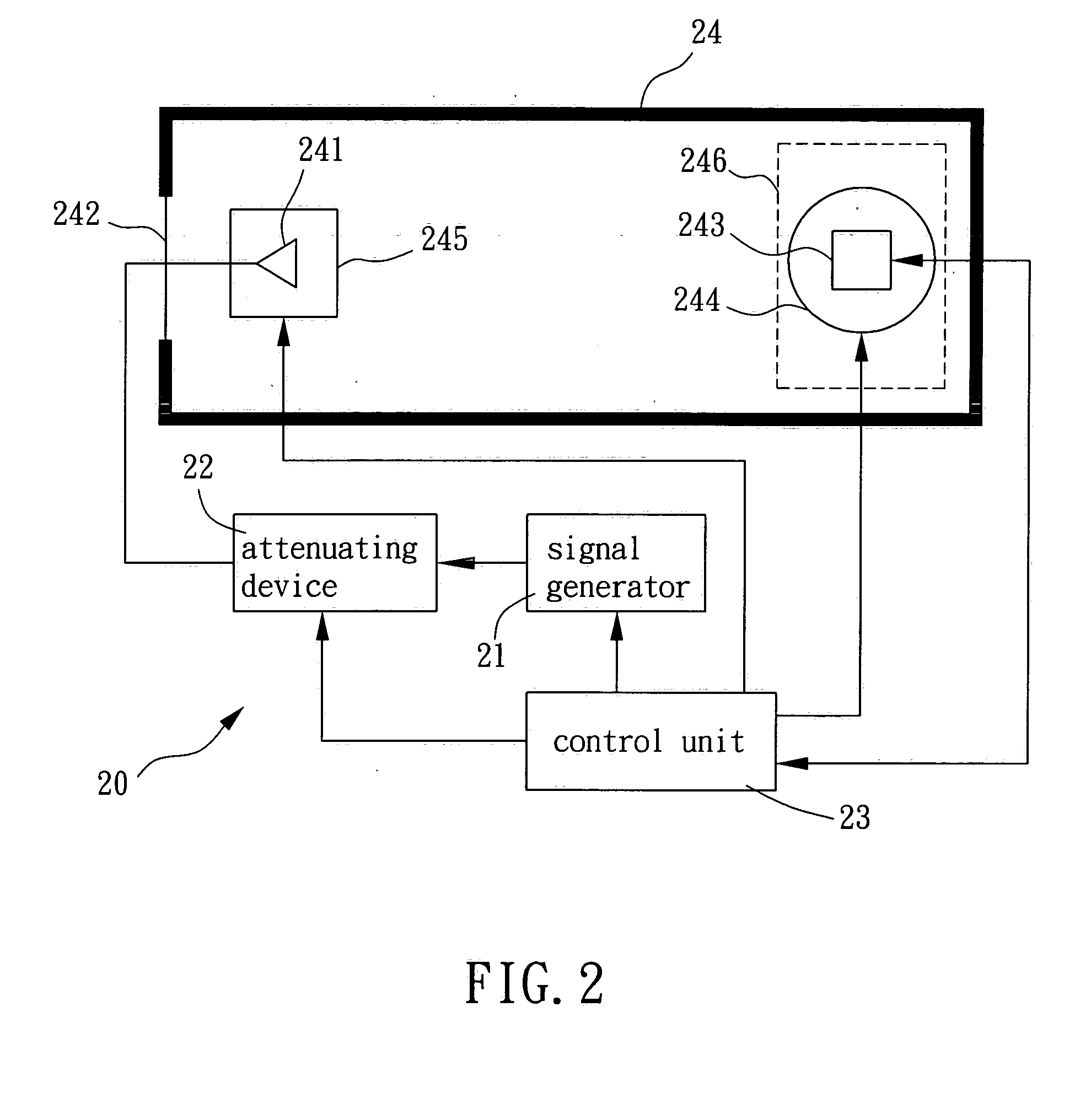
[0017]FIG. 2 is a block diagram showing a preferred embodiment of the system for multi-path simulation according to the present invention. As mentioned above, the system for multi-path simulation is used to simulate a wireless communication space with a direct transmission path and a main indirect transmission path. As shown in FIG. 2, the system 20 for multi-path simulation includes a signal generator 21 for generating a signal and an attenuating device 22 coupled to the signal generator 21 for attenuating the signal and generating an attenuated signal to simulate the signal attenuation during transmission. The system 20 also includes a control unit 23 coupled to the signal generator 21 and the attenuating device 22 for controlling signal generation of the signal generator 21 and adjusting an attenuation setting of the attenuating device 22. The system 20 also includes a shielded anechoic chamber 24, which is used to isolate external EMI and lower the r...


PUM


Abstract

The present invention provides a system and method for multi-path simulation that employs a shielded anechoic chamber to avoid external electromagnetic interference and other uncontrollable transmission paths during testing, and simulates a main indirect transmission path by a reflector within the chamber. An attenuating device is used to attenuate signals, thereby simulating the signal attenuation during transmission. The shielded anechoic chamber also includes a movable platform and a turntable, both controlled by a control unit, for carrying a dipole antenna and a wireless communication device to be tested respectively. The movable platform is used to shift the antenna, thereby simulating the phase shift between a direct path and a main indirect path of the system; the turntable is used to change the reception azimuth of the communication device, thereby measuring the performance of the device in various azimuth angles.

Description

BACKGROUND OF THE INVENTION [0001] (a). Field of the Invention [0002] The present invention relates in general to multi-path simulation, and more particularly to a system and method that employs a shielded anechoic chamber for avoiding external electromagnetic interference (EMI), a reflector thereof for simulating the main indirect path of a signal; and an attenuating device for simulating the signal attenuation during transmission. [0003] (b). Description of the Prior Arts [0004] In recent years, cellular phones and wireless local area networks (WLAN) are in widespread use with the rapid development of wireless communication technologies. In comparison with the signal transmission with a single physical path, the wireless signal transmission has an intrinsic multi-path phenomenon. The multi-path phenomenon means the wireless signal reaching the receiving antenna by two or more paths. The phenomenon results in the constructive or destructive interference, and phase shifting of the s...

Claims


Application Information

Patent Timeline
IPC IPC(8): H04B17/00
CPCH04B17/3912H04B17/391
Inventor LIU, I-RU
Owner ACCTON TECHNOLOGY CORPORATION
Learn More