Thermal print assembly

a technology of thermal dye and print assembly, applied in the direction of printing, duplicating/marking methods, coatings, etc., can solve the problems of thermal dye-donor elements and receiver elements used in thermal dye transfer systems, sticking and tearing of elements upon separation, rendering the receiver element useless, etc., to achieve good quality image or reduce the effect of

Active Publication Date: 2005-03-17
KODAK ALARIS INC
View PDF13 Cites 5 Cited by
  • Summary
  • Abstract
  • Description
  • Claims
  • Application Information

AI Technical Summary

Benefits of technology

Use of the print assembly having a stick preventative agent in each of the dye-donor element and the receiver element can reduce or prevent sticking between the dye-donor element and the receiver element during printing, including printing at high speed, for example, line speeds of 2.0 ms or less, and can result in a good quality image.

Problems solved by technology

A problem exists with many of the dye-donor elements and receiver elements used in thermal dye transfer systems.
At the high temperatures used for thermal dye transfer, many polymers used in these elements can soften and adhere to each other, resulting in sticking and tearing of the elements upon separation.
Areas of the dye-donor layer (other than the transferred dye) can adhere to the dye image-receiving layer, rendering the receiver element useless.
This is especially a problem for high-speed printing, wherein the printing technique can result in higher temperatures in order to transfer suitable amounts of dye.
However, moisture-curing resins can crosslink within the image-receiving layer, reducing dye diffusion and dye stability; can reduce coating uniformity; and can require additional processing steps during manufacture.
However, the use of such material in extrusion coated receiver elements is difficult because these materials degrade at high temperatures, resulting in unwanted reactions with other components of the receiver element.
U.S. Pat. No. 4,643,917 to Koshizuka describes silicone waxes for use in heat-sensitive transfer recording media, but does not achieve good quality images.

Method used


Image

  • Thermal print assembly
  • Thermal print assembly
  • Thermal print assembly

Examples


example

A thermal print assembly was constructed form a receiver element and dye-donor element. The materials and methods are set forth below.

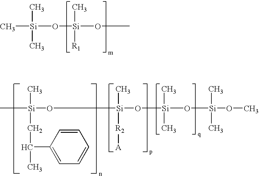
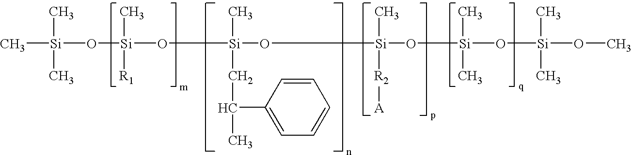
As used herein, MB50-315 is a commercially available 50:50 blend of bisphenol-A polycarbonate and ultrahigh MW polydimethyl siloxane from Dow Chemical Co., GP-70-S is a methylalkylaryl silicone from Genesee Polymers Corp., H3PO3 is phosphorous acid, PES is a polyester derived from 1,4-cyclohexanedicarboxylic acid, 1,4-cyclohexanedimethanol, 4,4′-bis(2-hydroxyethyl)bisphenol-A, and 2-ethyl-2-(hydroxymethyl)-1,3-propanediol, PC is bisphenol A polycarbonate, known as GE Lexan 151, obtained from General Electric Co; and DOS is dioctyl sebacate.

Receiver Element:

The receiver element was made as follows using the compositions of Table 1, wherein all compounds set forth in Table 1 are in percent by weight of the dye image-receiving layer:

TABLE 1MB50-Sample315GP-70SPESPCDOSH3PO3DRL-13—73.4618.195.330.02DRL-230.872.818.055.330.02DRL-331.272.5117.945.33...

example e-1

includes a stick preventative agent in both the dye-donor layer and the dye image-receiving layer. As compared to Example C-4, Example E-1 has less stick preventative agent in the dye image-receiving layer, producing acceptable results with regard to both toe and donor-receiver sticking.

As seen from the examples, a combination of a stick preventative agent in a dye-donor layer with a stick preventative agent in a dye image-receiving layer provides a synergistic effect in overcoming donor-receiver sticking, while minimizing the amount of stick preventative agent needed in one or both of the dye-donor layer and the dye image-receiving layer.


PUM

PropertyMeasurementUnit
weightaaaaaaaaaa
total weightaaaaaaaaaa
print speedsaaaaaaaaaa

Abstract

A print assembly is described, wherein the print assembly includes a dye-donor element having a dye-donor layer, wherein the dye-donor element includes a donor stick preventative agent; and a receiver having a dye image-receiving layer, wherein the receiver includes a receiver stick preventative agent of the formula:
wherein R1 is an alkyl chain of C9H19 or greater; R2 is an alkyl chain of C3H6 or greater; A is NH—R3, NHNH2, NHCO—R3, NH—R4—NH2, or NHCO—R4—NH2; R3 is an alkyl chain of C2H5 or greater; R4 is an alkyl chain of C2H4 or greater; m is from about 0 to 95 weight percent; n is from about 0 to about 70 weight percent; p is from 0 to about 40 weight percent; and q is from 0 to 95 weight percent, with the proviso that when m is 0, then n is 0, and R3 is an alkyl chain of C8H17 or greater, otherwise when m is greater than 0, n is from 0.1 to 70 weight percent, based on the total weight of the receiver stick preventative agent, and wherein the dye-donor element and receiver are in superposed position such that the dye-donor layer is adjacent the dye image-receiving layer. The use of stick preventative agents in both the dye-donor element and the receiver element can enable high speed printing without donor-receiver sticking.

Description

FIELD OF THE INVENTION A thermal print assembly having reduced donor-receiver sticking, and a method of printing using the print assembly, are described. BACKGROUND OF THE INVENTION Thermal transfer systems have been developed to obtain prints from pictures that have been generated electronically, for example, from a color video camera or digital camera. An electronic picture can be subjected to color separation by color filters. The respective color-separated images can be converted into electrical signals. These signals can be operated on to produce cyan, magenta, and yellow electrical signals. These signals can be transmitted to a thermal printer. To obtain a print, a black, cyan, magenta, or yellow dye-donor layer, for example, can be placed face-to-face with a dye image-receiving layer of a receiver element to form a print assembly which can be inserted between a thermal print head and a platen roller. A thermal print head can be used to apply heat from the back of the dye-do...

Claims


Application Information

Patent Timeline
Patent Type & Authority Applications(United States)
IPC IPC(8): B41M5/395B41M5/52
CPCB41M5/529B41M5/395
Inventor FOSTER, DAVID G.KUNG, TEH-MING
Owner KODAK ALARIS INC
Why Eureka
Try Eureka