Measuring circuit and a method for determining a characteristic of the impedance of a complex impedance element for facilitating characterization of the impedance thereof

a technology of complex impedance elements and measuring circuits, which is applied in the direction of resistance/reactance/impedence, measurement devices, instruments, etc., can solve the problems of cumulative errors introduced into signals by each separate circuit, complex impedance of many such sensors, and difficulty in determining the characteristic of the impedance of the complex impedance of the complex impedance of the complex sensor. achieve accurate matched, facilitate phase shift and amplitude change, and facilitate the effect of amplitud

Inactive Publication Date: 2005-03-17
ANALOG DEVICES INC
View PDF18 Cites 21 Cited by
  • Summary
  • Abstract
  • Description
  • Claims
  • Application Information

AI Technical Summary

Benefits of technology

[0043] The advantages of the invention are many. By virtue of the fact that the measuring circuit is implemented on a single chip, errors in the first output signal outputted by the measuring circuit are minimised. This is due to the fact that there is little or no accumulation of signal errors between the signal generating circuit and the first receiving circuit. Additionally, by virtue of the fact that the measuring circuit is implemented on a single chip, the respective components of the signal generating circuit and the first receiving circuit can be relatively accurately matched. Furthermore, when the measuring circuit is provided with a second receiving circuit, the components in the second receiving circuit can likewise be relatively accurately matched with the components in the signal generating circuit and the first receiving circuit. Thus, mismatch of the respective circuits of the measuring circuit due to ratiometric operation of the measuring circuit are minimised. Additionally, any drift in the measuring circuit can be minimised. Matching of the components of the signal generating circuit, and the first and second receiving circuits is further facilitated when the measuring circuit is implemented as an integrated circuit.
[0044] The measuring circuit according to the invention, in particular, facilitates the phase shift and amplitude change in a response signal from a complex impedance element, which is responsive to a stimulus signal applied to the complex impedance element to be readily and easily determined. Additionally, the frequency response of the complex impedance element can also be readily easily determined.
[0045] Additionally, the provision of the measuring circuit on a single chip facilitates synchronous timing of the entire measuring circuit. Furthermore, R-C timing components such as glitching and high frequency interference which arise where discrete elements are used are substantially eliminated in the measuring circuit according to the invention. Such R-C timing components in prior art circuits may result from track resistance and associated capacitance and inductance of the tracks of a printed ci...

Problems solved by technology

However, the impedance of many such sensors is complex, where the sensor includes a significant amount of reactance from capacitive or inductive elements.
Thirdly, a separate signal analysing circuit is required for analysing response signals from the sensor in response to the stimulus signal.
This results in many problems, in particular, each such circuit, namely, the signal generator, the signal conditioning circuits and the signal analysing circuit, each introduce errors into the respective signals.
Matching of the components of the various separate circuits for minimising mismatch errors is also problematical.
Furthermore, the errors introduced into the sign...

Method used


Image

  • Measuring circuit and a method for determining a characteristic of the impedance of a complex impedance element for facilitating characterization of the impedance thereof
  • Measuring circuit and a method for determining a characteristic of the impedance of a complex impedance element for facilitating characterization of the impedance thereof
  • Measuring circuit and a method for determining a characteristic of the impedance of a complex impedance element for facilitating characterization of the impedance thereof

Examples


Embodiment Construction

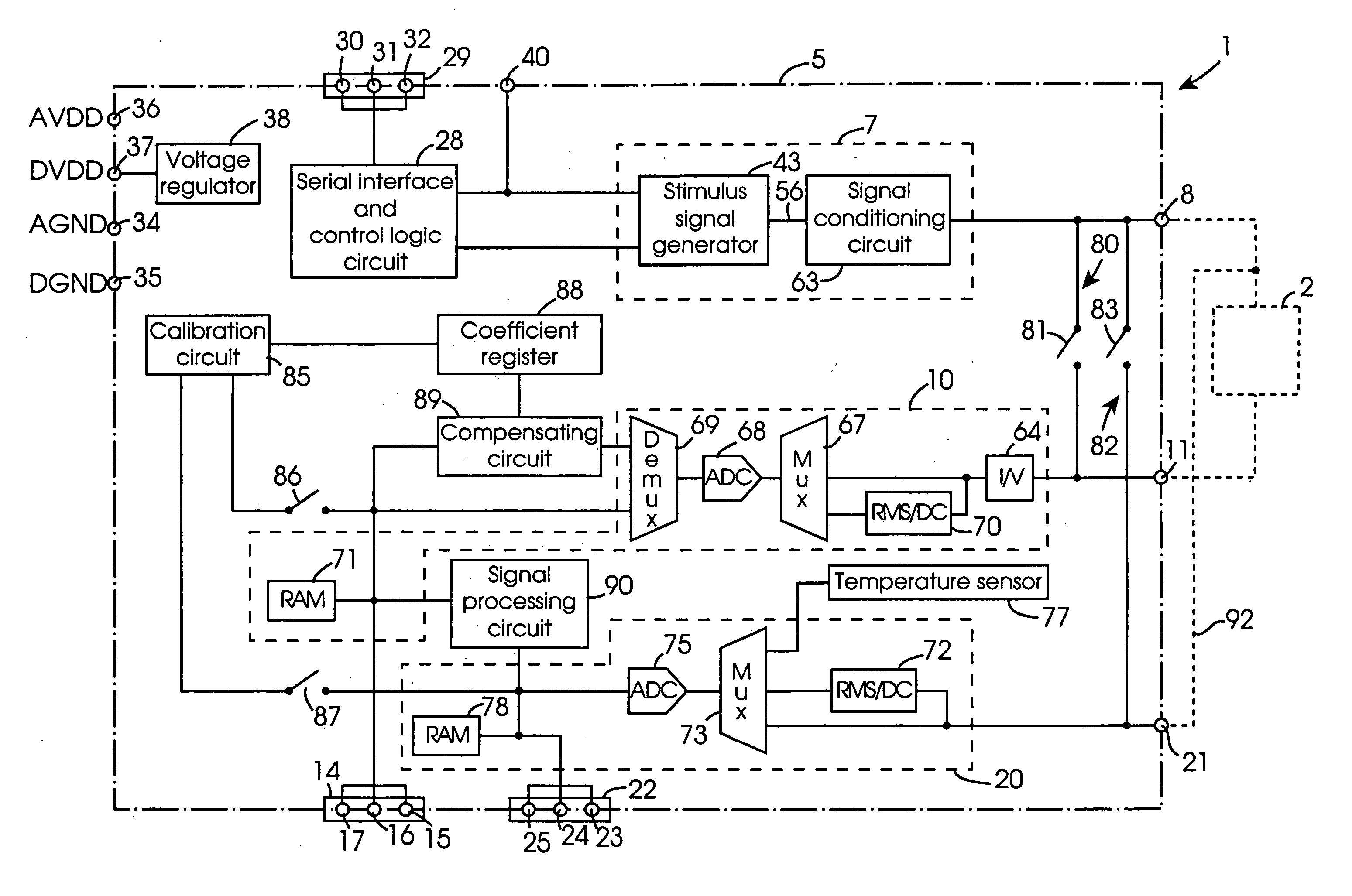
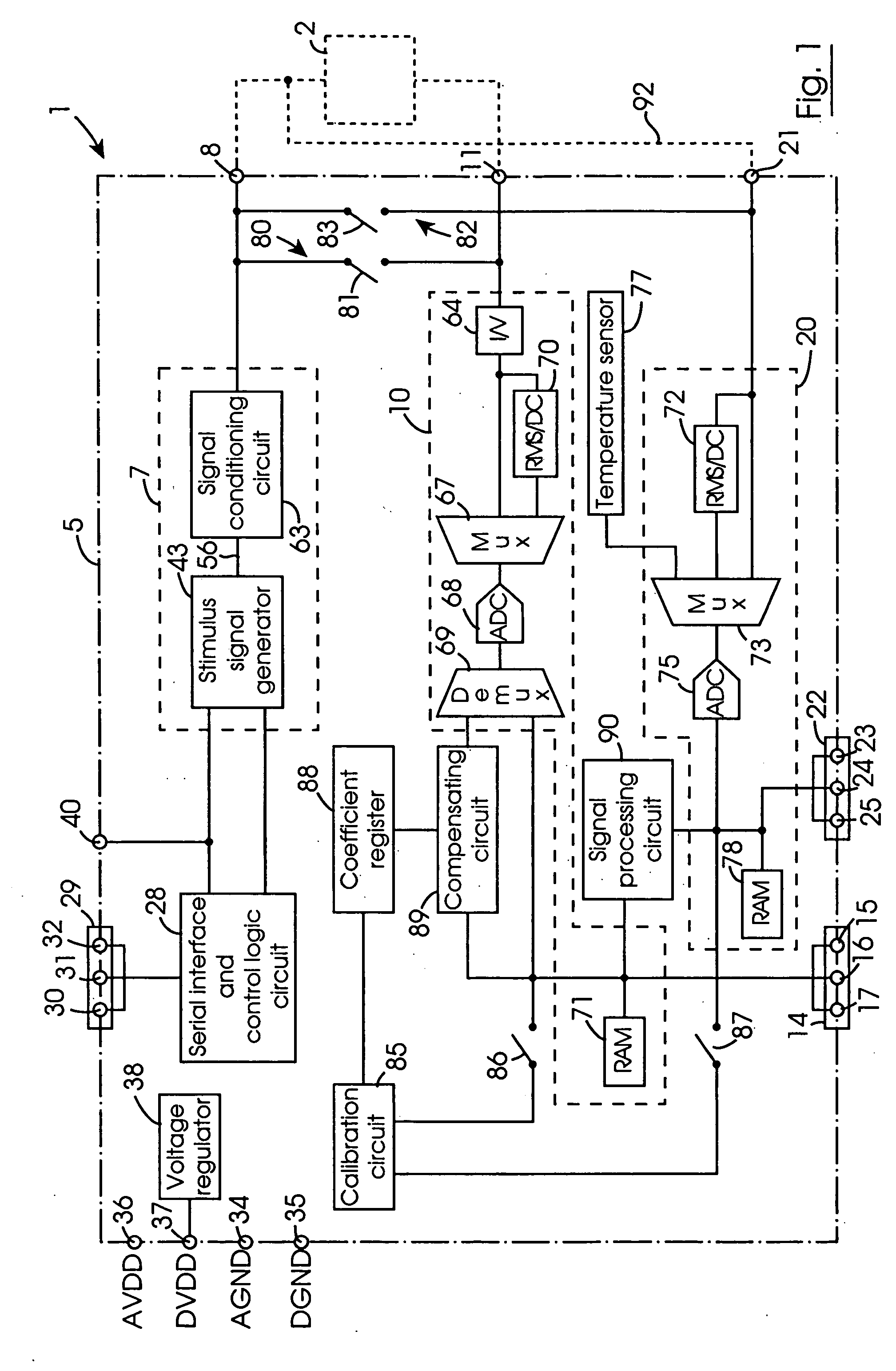
[0053] Referring to the drawings, there is illustrated a measuring circuit according to the invention, indicated generally by the reference numeral 1, for determining a characteristic of the impedance of a complex impedance element, namely, a complex impedance circuit 2 for facilitating characterization of the impedance of the complex impedance circuit 2. In this embodiment of the invention the measuring circuit 1 applies an analog voltage stimulus signal of selectable frequencies as will be described below to the complex impedance circuit 2, and is selectively operable for outputting a first output signal which is indicative of a phase shift and an amplitude change in the stimulus signal caused by the complex impedance of the circuit 2 at respective different frequencies. The complex impedance circuit 2 may be any impedance circuit or element in which the impedance is complex, for example, a circuit with complex impedance, a characteristic of the impedance of which is to be determi...


PUM


Abstract

A single chip integrated circuit measuring circuit (1) for determining a characteristic of the impedance of an external complex impedance circuit (2) for facilitating characterization of the impedance of the complex impedance circuit (2) comprises a signal generating circuit (7) for generating a variable frequency stimulus signal for applying to the complex impedance circuit (2). A first receiving circuit (10) receives a response signal from the complex impedance circuit (2) in response to the stimulus signal and conditions the response signal. A first analog-to-digital converter (68) converts the conditioned response signal to a first digital output signal, which is read from the first analog-to-digital converter (68) through a first digital output port (14). The response signal from the complex impedance circuit (2) is a current signal, and a current to voltage converter circuit (64) converts the response signal to a voltage signal. A first RMS to DC level converting circuit (70) converts the AC voltage of the response signal to a DC voltage level, and a fourth multiplexer (67) selectively applies the voltage response signal or the DC voltage level signal to the first analog-to-digital converter (68), depending on whether it is desired that the first digital output signal should be indicative of the phase shift or amplitude change in the response signal relative to the stimulus signal. A second receiving circuit (20) receives the stimulus signal, and similarly converts the stimulus signal to a second digital output signal for facilitating comparison of the response signal with the stimulus signal.

Description

FIELD OF THE INVENTION [0001] The present invention relates to a measuring circuit for determining a characteristic of the impedance of a complex impedance element for facilitating characterization of the impedance thereof, and in particular, though not limited to such a measuring circuit for determining a characteristic of the impedance of an impedance based sensor for in turn facilitating measuring the change in impedance of such a sensor as a result of an external effect. The invention also relates to a method for determining a characteristic of the impedance of a complex impedance element for facilitating characterization of the impedance thereof, and in particular, though not limited to such a method for determining a characteristic of the impedance of an impedance based sensor for in turn facilitating measuring the change in impedance of such a sensor as a result of an external effect. BACKGROUND TO THE INVENTION [0002] Impedance based sensors are well known, and are commonly ...

Claims


Application Information

Patent Timeline
IPC IPC(8): G01R27/02
CPCG01R27/02
Inventor CAFFREY, JAMES F.SLATTERY, COLM F.O'GRADY, ALBERT
Owner ANALOG DEVICES INC
Why Eureka
Try Eureka