Multistage inverse quantization having the plurality of frequency bands

a multi-stage, frequency band technology, applied in the field of audio signal coding apparatus for coding an audio signal, can solve the problems of large amount of memory, large amount of calculation, and inability to obtain high-quality sound at a high compression ratio, and achieve less quantization errors, dramatic heightened effects, and high quantization efficiency

Inactive Publication Date: 2005-03-17
PANASONIC CORP
View PDF11 Cites 37 Cited by
  • Summary
  • Abstract
  • Description
  • Claims
  • Application Information

AI Technical Summary

Benefits of technology

Furthermore, according to the audio signal coding apparatus, and decoding apparatus, or coding and decoding method of the present invention, a normalization means is provided before the quantization means, and normalization of an input audio signal is carried out before quantization. Therefore, the normalization means and the quantization means perform coding while exhibiting their full abilities, whereby highly efficient quantization is carried out without losing the data quantity possessed by the original audio signal and, therefore, with less quantization error, and the effect is dramatically heightened according to the kind of the audio signal. Furthermore, as described above, allocation of data quantity during quantization is carried out so as to allocate, alternately, data quantity contributing to expansion of a reproduced band and data quantity contributing to improvement of quality. When the data quantity at the receiving end is limited, inverse quantization is carried out only in a narrow band and a shallow region. However, by expanding the inverse quantization alternately in the direction to broaden the band and the direction to increase the depth of the inverse quantization to increase the data quantity at the receiving end, a desired quantity of data of the coded audio signal can be decoded regardless of the quantity of data transmitted from the coding apparatus. Accordingly, by varying the quantity of data to be decoded according to the communication environment or the like on the receiving end, high-definition sound quality can be obtained stably even when an ordinary publi...

Problems solved by technology

However, in the conventional audio signal coding and decoding apparatuses, coding and decoding must be carried out with a fixed data quantity to obtain a satisfactory sound quality and, therefore, it is impossible to obtain a high-quality sound at a high compression ratio.
However, when the number of...

Method used


Image

  • Multistage inverse quantization having the plurality of frequency bands
  • Multistage inverse quantization having the plurality of frequency bands
  • Multistage inverse quantization having the plurality of frequency bands

Examples


embodiment 1

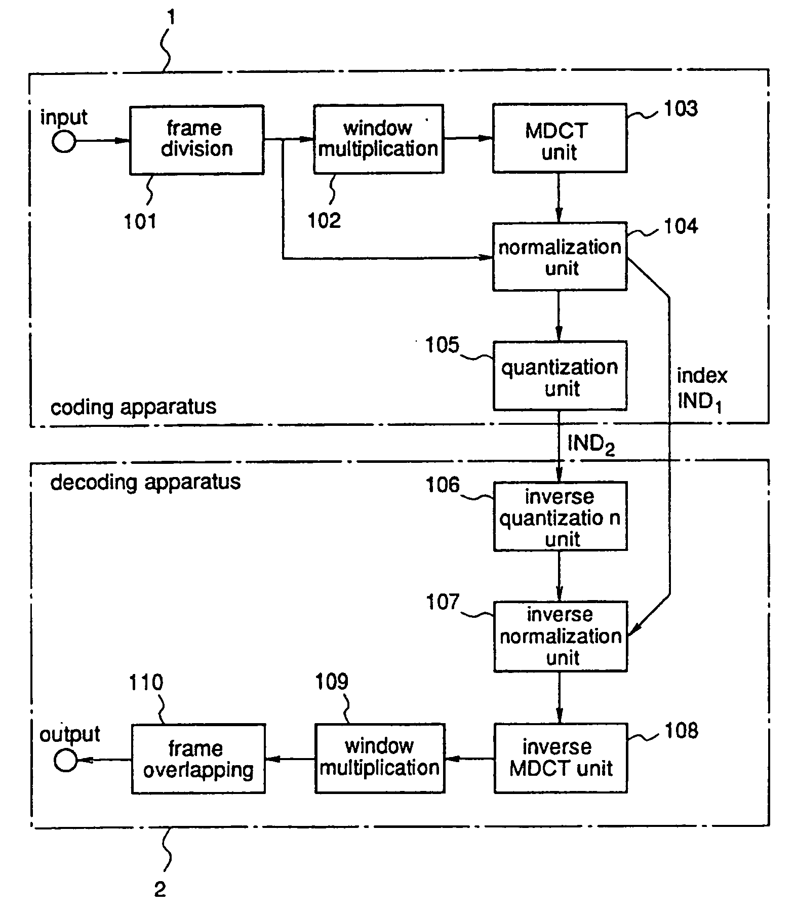
FIG. 1 is a diagram illustrating the entire structure of audio signal coding and decoding apparatuses according to a first embodiment of the invention. In FIG. 1, reference numeral 1 denotes a coding apparatus, and 2 denotes a decoding apparatus. In the coding apparatus 1, reference numeral 101 denotes a frame division unit that divides an input signal into a prescribed number of frames; 102 denotes a window multiplication unit that multiplies the input signal and a window function on the time axis; 103 denotes an MDCT unit that performs modified discrete cosine transform; 104 denotes a normalization unit that receives both of the time axis signal output from the frame division unit 101 and the MDCT coefficients output from the MDCT unit 103 and normalizes the MDCT coefficients; and 105 denotes a quantization unit that receives the normalized MDCT coefficients and quantizes them. Although the MDCT is employed for time-to-frequency transform in this embodiment, discrete Fourier trans...

embodiment 2

Next, an audio signal coding apparatus according to a second embodiment of the invention will be described using FIG. 5. In this second embodiment, only the structure of the quantization unit 105 in the coding apparatus 1 is different from that of the first embodiment and, therefore, only the structure of the quantization unit will be described hereinafter. In FIG. 5, reference numeral 501 denotes a first sub-quantization unit, 502 denotes a second sub-quantization unit, and 503 denotes a third sub-quantization unit. This fifth embodiment is different in structure from the first embodiment in that the first quantization unit 501 divides the input MDCT coefficients into three bands (high-band, intermediate-band, low-band) and quantizes the respective bands independently, and quantization sections for the respective bands, which constitute the first sub-quantization unit 501, correspond to so-called “divided vector quantizers”. Generally, when quantization is carried out using a meth...

embodiment 3

An audio signal coding apparatus according to a third embodiment of the present invention will be described using FIG. 6. In this third embodiment, since only the structure of the quantization unit 105 in the coding apparatus 1 is different from that of the above-mentioned first embodiment, only the structure of the quantization unit will be explained. In FIG. 6, reference numeral 601 denotes a first sub-quantization unit, 602 denotes a first quantization band selection unit, 603 denotes a second sub-quantization unit, 604 denotes a second quantization band selection unit, and 605 denotes a third sub-quantization unit. This third embodiment is different in structure from the second embodiment in that the first quantization band selection unit 602 and the second quantization band selection unit 604 are added.

Hereinafter, the operation will be described. The first quantization band selection unit 602 calculates a band, of which MDCT coefficients are to be quantized by the second su...


PUM


Abstract

With respect to audio signal coding and decoding apparatuses, there is provided a coding apparatus that enables a decoding apparatus to reproduce an audio signal even through it does not use all of data from the coding apparatus, and a decoding apparatus corresponding to the coding apparatus. A quantization unit constituting a coding apparatus includes a first sub-quantization unit comprising sub-quantization units for low-band, intermediate-band, and high-band; a second sub-quantization unit for quantizing quantization errors from the first sub-quantization unit; and a third sub-quantization unit for quantizing quantization errors which have been processed by the first sub-quantization unit and the second sub-quantization unit.

Description

TECHNICAL FIELD The present invention relates to an audio signal coding apparatus for coding an audio signal, such as a voice signal or a music signal and, more particularly, to an apparatus for transforming an audio signal from time-domain to frequency-domain using a method like orthogonal transformation, and efficiently coding the transformed signal so that it is expressed with less code streams as compared with the original audio signal, and to a decoding apparatus having a structure capable of decoding a high-quality and broad-band audio signal using all or only a portion of the coded streams which are coded signals. Furthermore, the invention relates to an audio signal coding and decoding method. BACKGROUND ART Various methods for efficiently coding and decoding audio signals have been proposed. Especially for an audio signal having a frequency band exceeding 20 kHz such as a music signal, an MPEG audio method has been proposed in recent years. In the coding method represente...

Claims


Application Information

Patent Timeline
IPC IPC(8): G10L19/00G10L21/02
CPCG06Q20/10G10L19/038G10L19/0212G06Q20/102G10L19/032G06Q30/04
Inventor NORIMATSU, TAKESHIMIYASAKA, SHUJINAKATOH, YOSHIHISATSUSHIMA, MINEOISHIKAWA, TOMOKAZU
Owner PANASONIC CORP
Why Eureka
Try Eureka