Magnetic roller

a magnetic roller and roller body technology, applied in the field of rollers, can solve the problems of wrinkles, other imperfections in the web, and the webs used in the manufacture of disposable diapers, and achieve the effect of strengthening the magnetic coupling

Inactive Publication Date: 2005-03-24
MARTIN AUTOMATIC
View PDF15 Cites 14 Cited by
  • Summary
  • Abstract
  • Description
  • Claims
  • Application Information

AI Technical Summary

Benefits of technology

[0016] Certain embodiments of the present invention provide a web handling system, including a plurality of rolls of web material, a splice unit configured to splice a first end of web material from a first of said plurality of rolls to a second end of web material from a second of said plurality of rolls, and a plurality of roller assemblies supporting the web material throughout the web handling system. Each of the plurality of roller assembl

Problems solved by technology

The webs used in manufacturing disposable diapers, especially the webs of nonwoven materials, tend to be relatively fragile, and this has often limited the forces that can be exerted in the webs during handling.
The surfaces of web-handling rollers are usually shaped to a desired profile and are typically required to be rigid, due to the fact that surface imperfections and flexure in web rollers may lead to wrinkles and other imperfections in the web.
As a result, such web rollers have a substantial amount of inertia.
This equipment is generally relatively expensive and also requires space on the already crowded, short-of-space manufacturing floor.
Also, relatively large amounts of energy must be expended to control the motion of high-inertia rollers.
In addition, such standard web rollers have also required relatively heavy bearings for support.
Heavy bearings, in turn, have a substantial amount of friction.
A disadvantage, however, to supporting the web material directly with air is

Method used


Image

  • Magnetic roller
  • Magnetic roller
  • Magnetic roller

Examples


Embodiment Construction

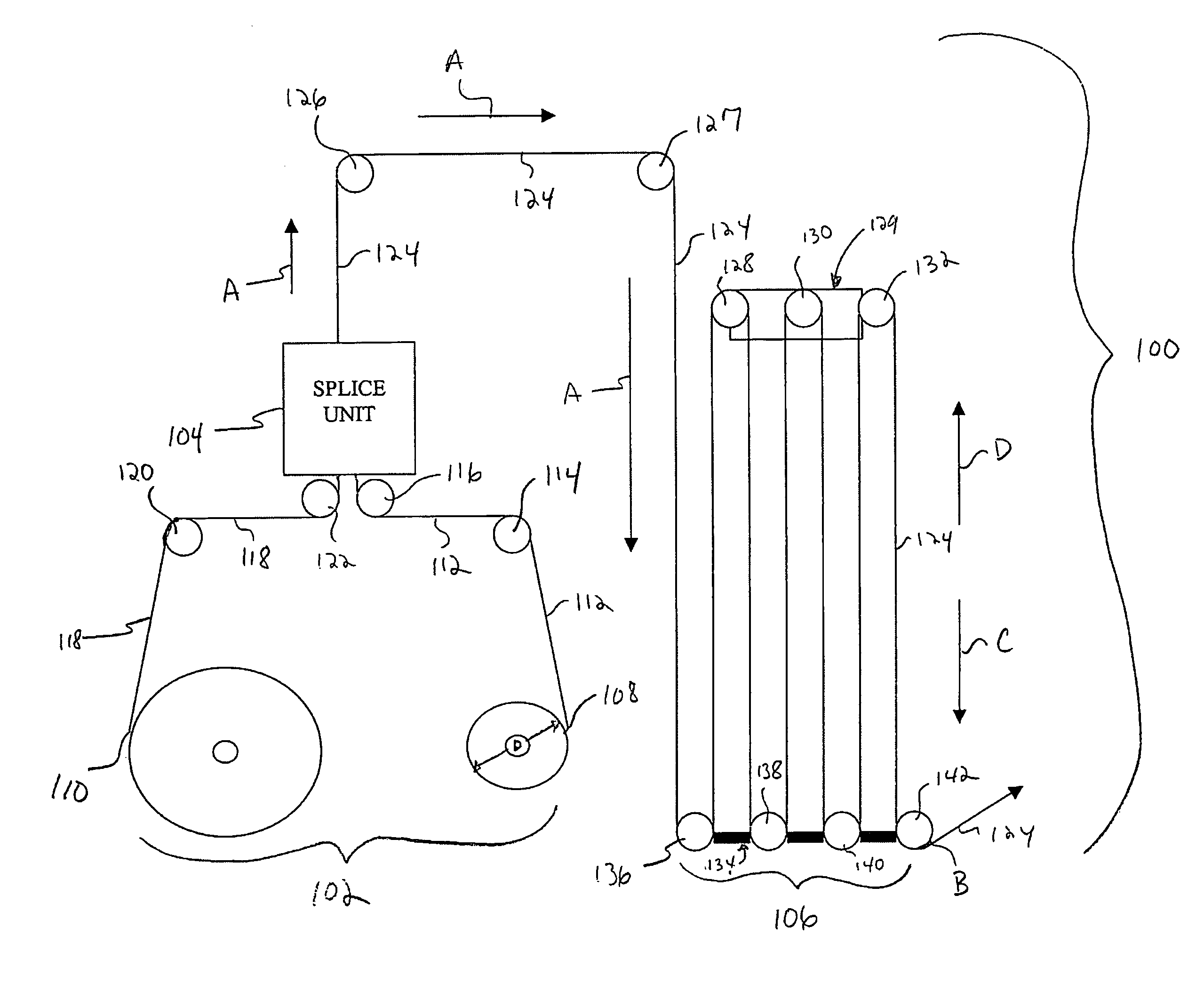
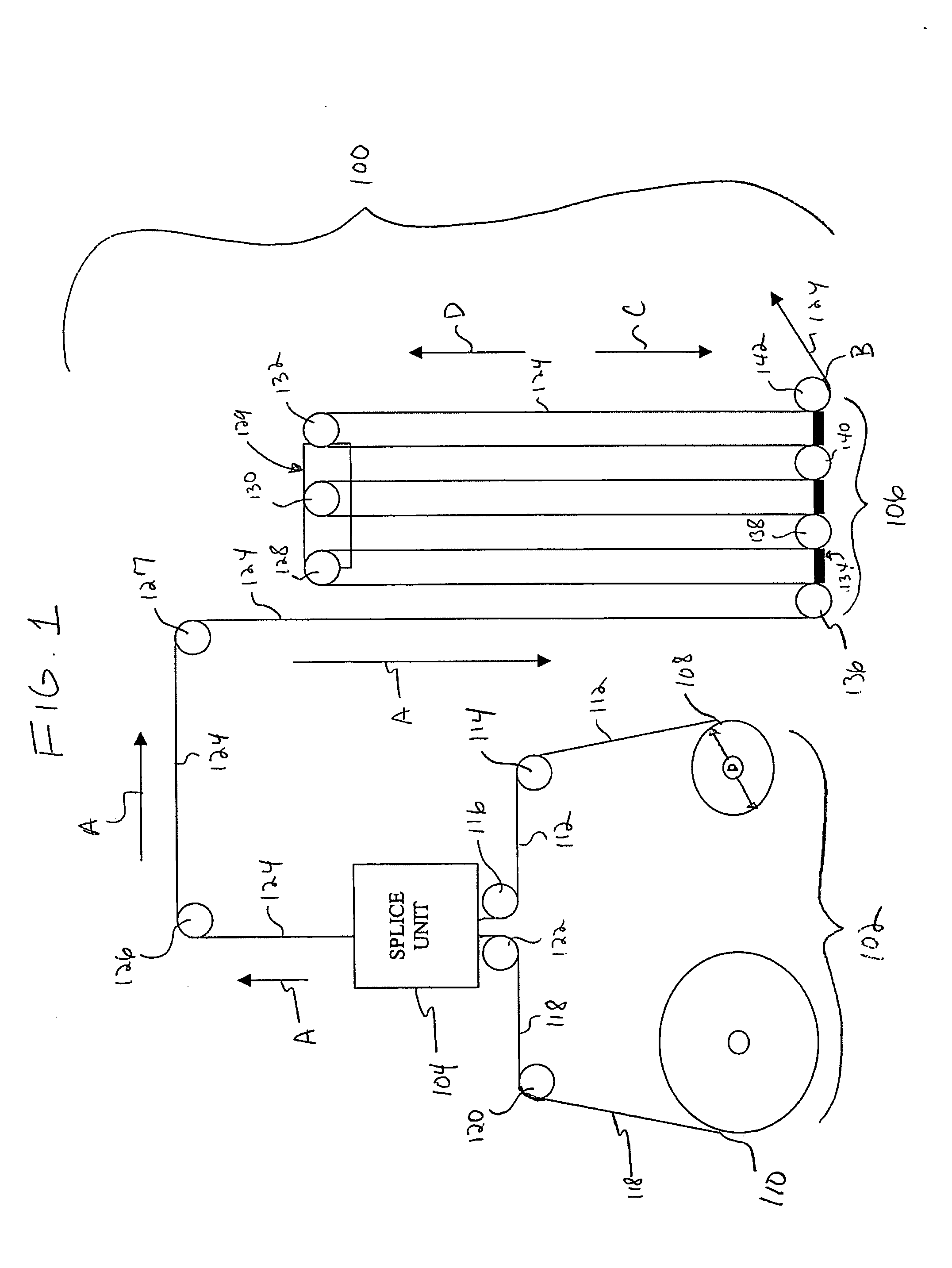
[0027]FIG. 1 illustrates a schematic diagram of a web handling system 100, according to an embodiment of the present invention. The system 100 includes a web feed roll assembly 102, a splice unit 104, and a festoon assembly 106.

[0028] The web feed roll assembly 102 includes a first roll 108 of web material and a second roll 110 of web material. Web material 112 is drawn off the first roll 108 over a magnetic roller 114 to a magnetic roller 116 and through the splice unit 104. The web material 118 may then be hand drawn from the second roll 110 over a magnetic roller 120 to a magnetic roller 122, and into the splice unit 104, which splices the head end of the web material 118 to the tail end of the web material 112. When the first roll 108 is reduced to a predetermined diameter D, the first roll 108 is stopped so that web material 112 is no longer drawn therefrom. The web material 112 is then spliced in the splice unit 104 to web material 118. The spliced web material 124 passes thr...


PUM


Abstract

A magnetic roller system configured for use within a web handling system, the system including a drive hub, and a roller that is magnetically coupled to the drive hub. The roller is configured to support a web of material. An adjustable gap is defined between the drive hub and the roller. The strength of the magnetic coupling increases as the adjustable gap decreases.

Description

RELATED APPLICATIONS [0001] This application relates to and claims priority benefits from U.S. Provisional Patent Application No. 60 / 495,209 entitled “Improved Magnetic Roller,” filed Aug. 14, 2003, which is incorporated by reference herein in its entirety.BACKGROUND OF THE INVENTION [0002] Embodiments of the present invention generally relate to rollers for handling moving webs of various materials, and more particularly, to improved rollers configured to handle relatively high speed, fragile webs, such as webs of nonwoven materials utilized in the manufacture of disposable diapers and the like. [0003] Manufacturers, whose processes involve web handling, continually seek higher web processing speeds. Disposable diaper manufacturers are illustrative of such manufacturers because increasing the speed of the webs utilized in making disposable diapers can significantly reduce manufacturing costs on a per diaper basis. The webs used in manufacturing disposable diapers, especially the we...

Claims


Application Information

Patent Timeline
IPC IPC(8): B65H19/14B65H19/18H02P15/00
CPCB65H19/14B65H19/1852B65H2403/73B65H2403/724B65H19/1873
Inventor SEABERG, DAVID LAVERNEWARD, JAMES K.ROBERTS, ZACHARY STEPHANSCHLITTLER, KENDALL EUGENE
Owner MARTIN AUTOMATIC
Why Eureka
Try Eureka