Maximum sensitivity optical scanning system

a scanning system and maximum sensitivity technology, applied in the field of optical scanning systems, can solve the problems of inability to know the exact value of the detector, inability to adjust the components manually, and inability to accurately detect the detector, etc., to achieve the effect of increasing the signal strength, increasing the accuracy, and increasing the accuracy

Inactive Publication Date: 2005-03-24
AGILENT TECH INC
View PDF3 Cites 3 Cited by
  • Summary
  • Abstract
  • Description
  • Claims
  • Application Information

AI Technical Summary

Benefits of technology

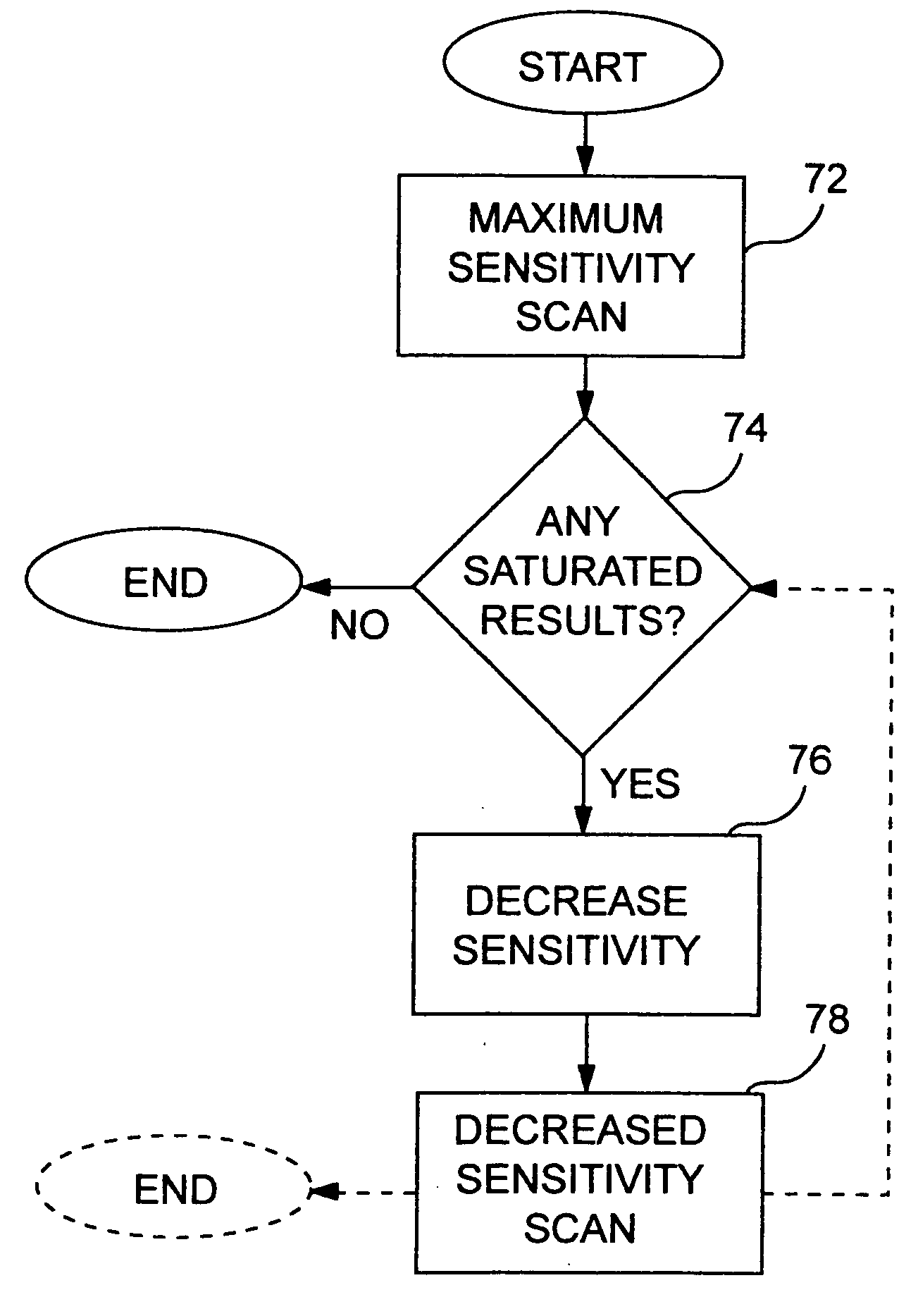
[0010] The system of the present invention handles the reality of photobleaching in a different fashion. Rather than scanning samples and adjusting system limits to avoid photobleaching of unscanned samples during detection steps as in the Bengtsson patent, the present invention acquires valid data from some sample while the signal associated with other data is saturated. In this manner, low value signals are accurately detected with greatest accuracy. Rescanning areas producing more intense signals for detection after exposure resulting in photobleaching is not problematic since the relatively higher signal strength enables adequate data acquisition despite the deleterious effect of repeated light exposure.

Problems solved by technology

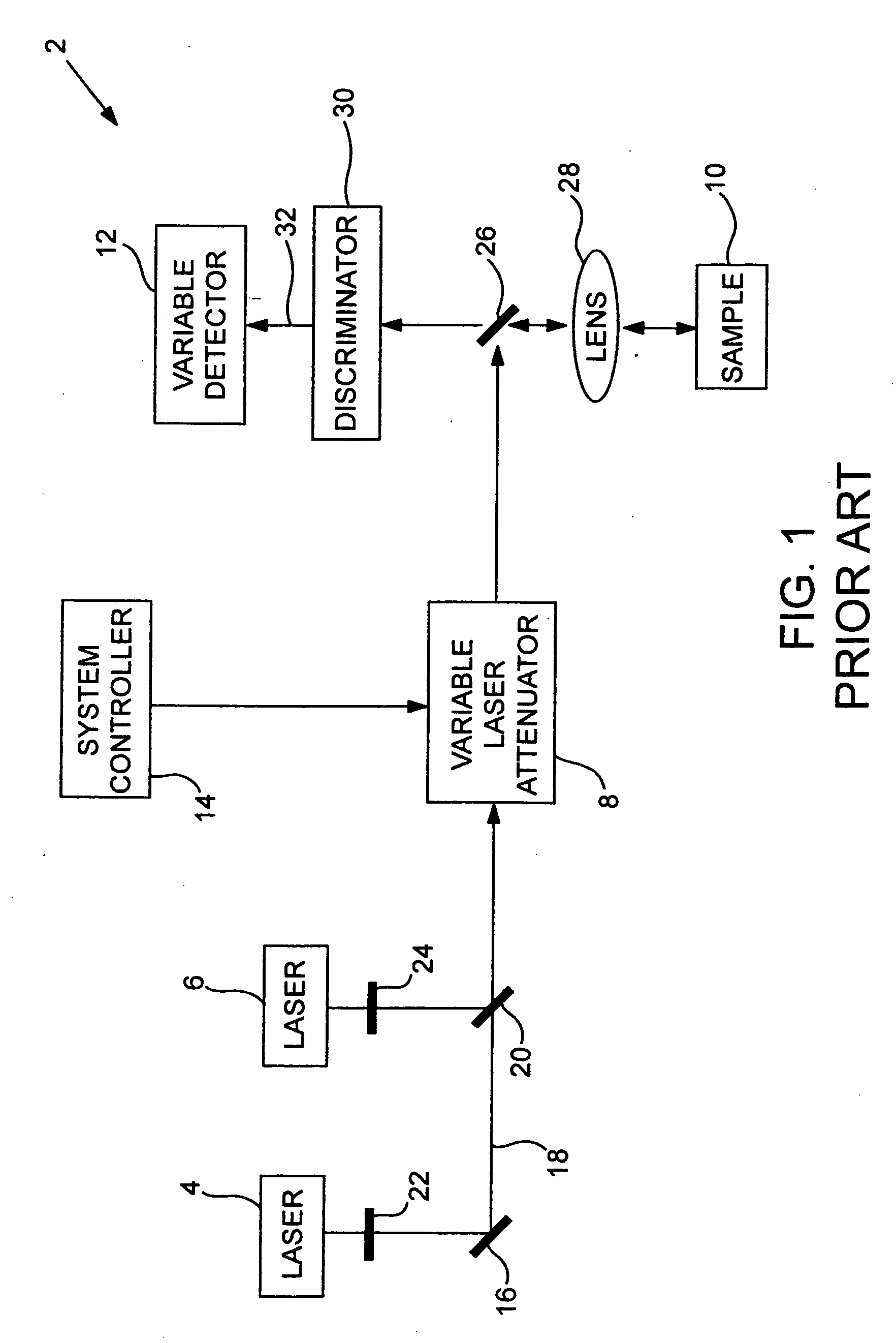
Further, the user does not know how high or low to set the gain of a detector that collects emitted fluorescence and produces a corresponding data signal.
Accordingly, manual adjustment of these components is time consuming, particularly since adjustment of either one of them may require a re-adjustment of the other.
If the excitation power and / or attenuator gain are set too low (i.e., detector sensitivity is too far reduced), the system may not accurately distinguish between different lower levels of emitted fluorescence.
), the general view is that such saturation results in a failure to make accurate measurements.
With the other lines, however, the same problems encountered with manual scanning and tuning optical system attenuation or excitation system gain from photo-bleaching as a result of rescanning are encountered.
The risk of damage to the sample is further increased when multiple channels are used.

Method used


Image

  • Maximum sensitivity optical scanning system
  • Maximum sensitivity optical scanning system
  • Maximum sensitivity optical scanning system

Examples


example

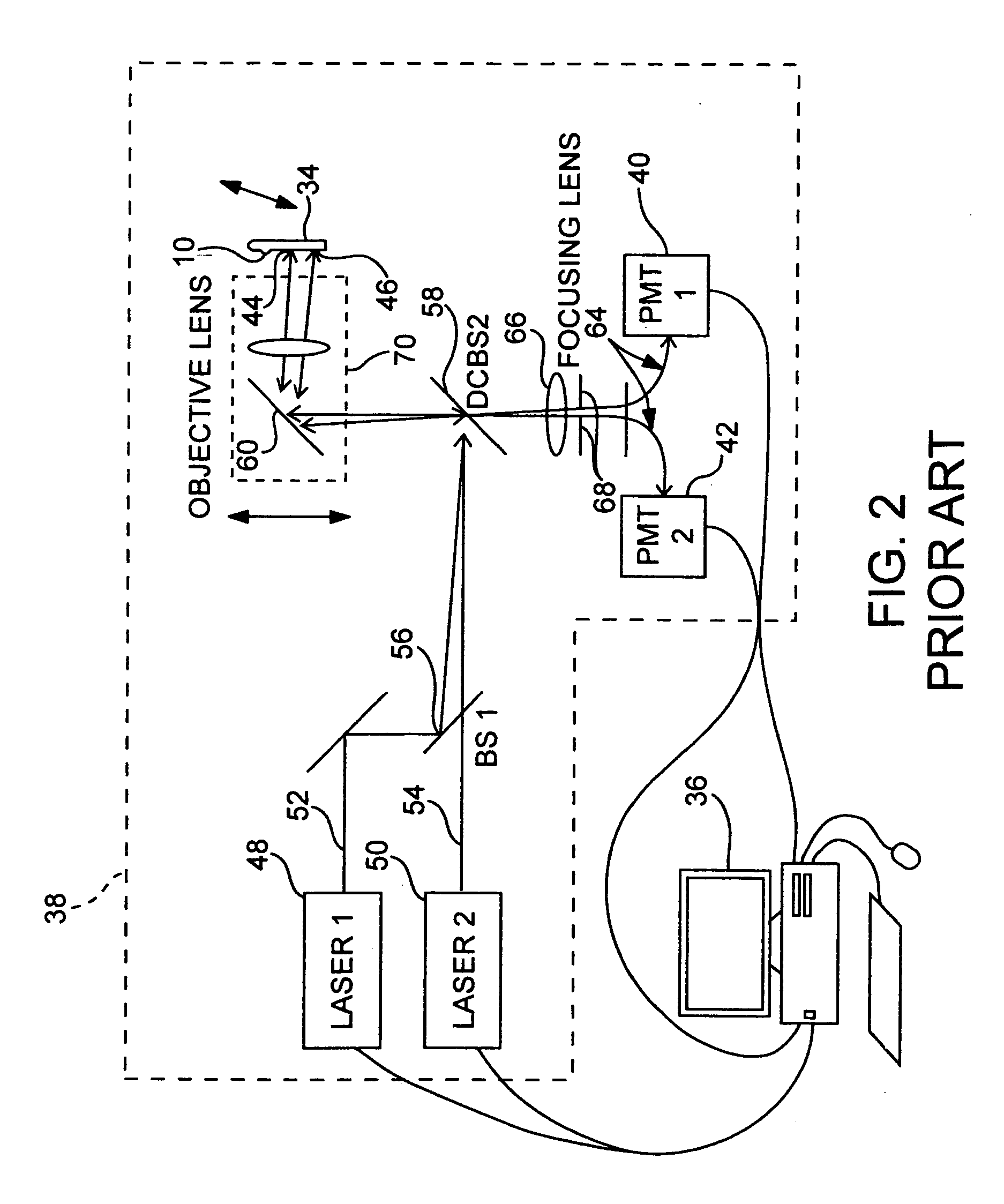
[0053] The present invention is preferably used in conjunction with arrays of polymeric binding agents spotted onto a surface—possibly by ink-jet printheads, by pin spotting or otherwise. The arrays will usually include at least two distinct polymers that differ by monomeric sequence immobilized on, e.g., covalently or non-covalently attached to, different and known locations on the substrate surface. Each distinct polymeric sequence of the array is typically present as a composition of multiple copies of the polymer on the substrate surface, e.g. as a spot on the surface of the substrate. The number of distinct polymeric sequences, and hence spots or similar structures, present on the array may vary, but is generally at least 2, usually at least 5 and more usually at least 10, where the number of different spots on the array may be as a high as 50, 100, 500, 1000, 10,000 or higher, depending on the intended use of the array. The spots of distinct polymers present on the array surfa...


PUM

PropertyMeasurementUnit
diameteraaaaaaaaaa
optical scanningaaaaaaaaaa
fluorescenceaaaaaaaaaa

Abstract

A maximum sensitivity optical scanning system is disclosed. It finds use in a variety of applications, including the reading of biopolymeric arrays. It operates by scanning sample at a setting selected to result in signal saturation for some, but not all available data. Subsequent scans of the same area are taken at lower sensitivity settings (in terms of detector gain and / or excitation light source gain or attenuation) and data from at least the previously saturated regions is obtained. If system sensitivity is set too low to produce useful results, optional features may adjust sensitivity upward and follow with an increased sensitivity scan as a remedial measure. Full signal sensitivity is better preserved as most needed in taking data for the weakest signals first with the high-level scan. Data for sample producing stronger signals that can better tolerate photobleaching is then taken in one way or another.

Description

[0001] This application claims priority to copending application Ser. No. 10 / 087,619, filed Feb. 28, 2002, under 35 U.S.C. 120, the entirety of which is incorporated herein by reference.FIELD OF THE INVENTION [0002] This invention relates to optical scanners and, more particularly, to approaches for scanning low signal emission samples without photo-bleaching. BACKGROUND OF THE INVENTION [0003] Optical scanners find use in performing detection for various experiments, assays and the like. They are often used in array analysis systems for detection of surface bound binding complexes in genomic and proteomic applications. In fluorescence optical scanners, fluorescence emitted from a sample that has been excited by a light signal is collected and detected. [0004] Often, a user has little idea of the brightness of the fluorescence that will be emitted by a particular sample. Accordingly, the user does not know a priori how high or low to set the attenuation of an attenuator that control...

Claims


Application Information

Patent Timeline
Patent Type & Authority Applications(United States)
IPC IPC(8): G01N21/64
CPCG01N21/6456G01N2021/6419G01N2021/6484G01N2021/6463G01N2021/6441
Inventor CURRY, BO U.DORSEL, ANDREAS N.SCHLEIFER, KYLE J.SILLMAN, DEBRA A.
Owner AGILENT TECH INC
Why Eureka
Try Eureka