Method and sensing device for motion detection in an optical pointing device, such as an optical mouse

a motion detection and optical mouse technology, applied in the field of pointing devices, can solve the problems of inapplicability of the above-mentioned motion detection technique, inability to derive any measurement of the relative motion between the optical sensing device and the illuminated surface, and inability to compare the light intensity between neighbouring pixels to provide any information, etc., to achieve the effect of increasing the complexity of processing, increasing the contrast of surface patterns, and great sensitiveness

Inactive Publication Date: 2005-03-24
EM MICROELECTRONIC-MARIN
View PDF7 Cites 105 Cited by
  • Summary
  • Abstract
  • Description
  • Claims
  • Application Information

AI Technical Summary

Benefits of technology

In addition, the invention exhibits great sensitiveness and allows a wide range of illumination angles to be used instead of the required low illumination angles used to increase the contrast of the surface pattern in the correlation techniques of U.S. Pat. No. 5,578,813, No. 5,644,139 and No. 5,686,720. The present invention may furthermore be based on an analysis of grayscale images without this increasing the complexity of the processing.

Problems solved by technology

A serious problem however arises when applying the above motion detection scheme to optical pointing devices where the illuminated surface does not exhibit a predetermined pattern, such as in the case of an optical “ball-less” mouse which directly uses light reflected from a random surface, such as paper or the surface of a desk.
Since specific and well-defined patterns of edges cannot clearly be detected and tracked, it is accordingly impossible to derive any measurement of the relative motion between the optical sensing device and the illuminated surface.
In practice, the above-mentioned motion detection technique is therefore not applicable and alternative solutions need to be found.
According to this motion detection principle, comparison of light intensity between neighbouring pixels is however not performed to provide any information concerning spatial intensity differences (i.e. edges) between neighbouring pixels.
This leads to constraints in the construction of the optical pointing device.
In addition, image frame correlation techniques as proposed in these documents show some limitations when analysing grayscale image frames, the complexity of the correlation process increasing exponentially with the depth of intensity of the image.
In practice, the application of the above correlation techniques to motion detection in optical device is limited to the analysis of binary black-and-white images.

Method used


Image

  • Method and sensing device for motion detection in an optical pointing device, such as an optical mouse
  • Method and sensing device for motion detection in an optical pointing device, such as an optical mouse
  • Method and sensing device for motion detection in an optical pointing device, such as an optical mouse

Examples


Embodiment Construction

Two algorithms will be described in the following description. The first algorithm will be referred to as “Peak / Null Motion Detection” algorithm and the second as “Local Edge Direction Motion Detection” algorithm. Both algorithms use only edge direction data from the pixel array.

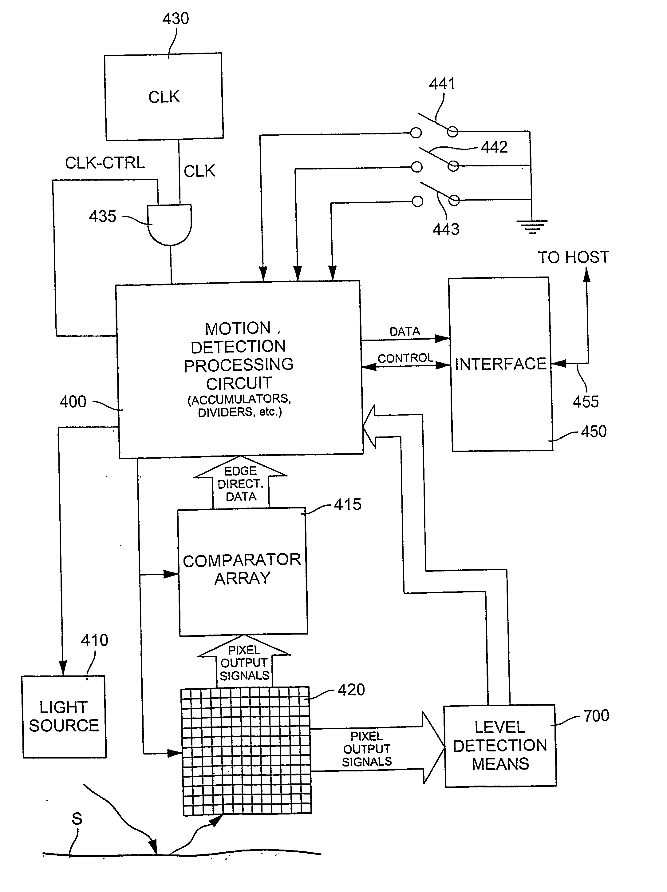
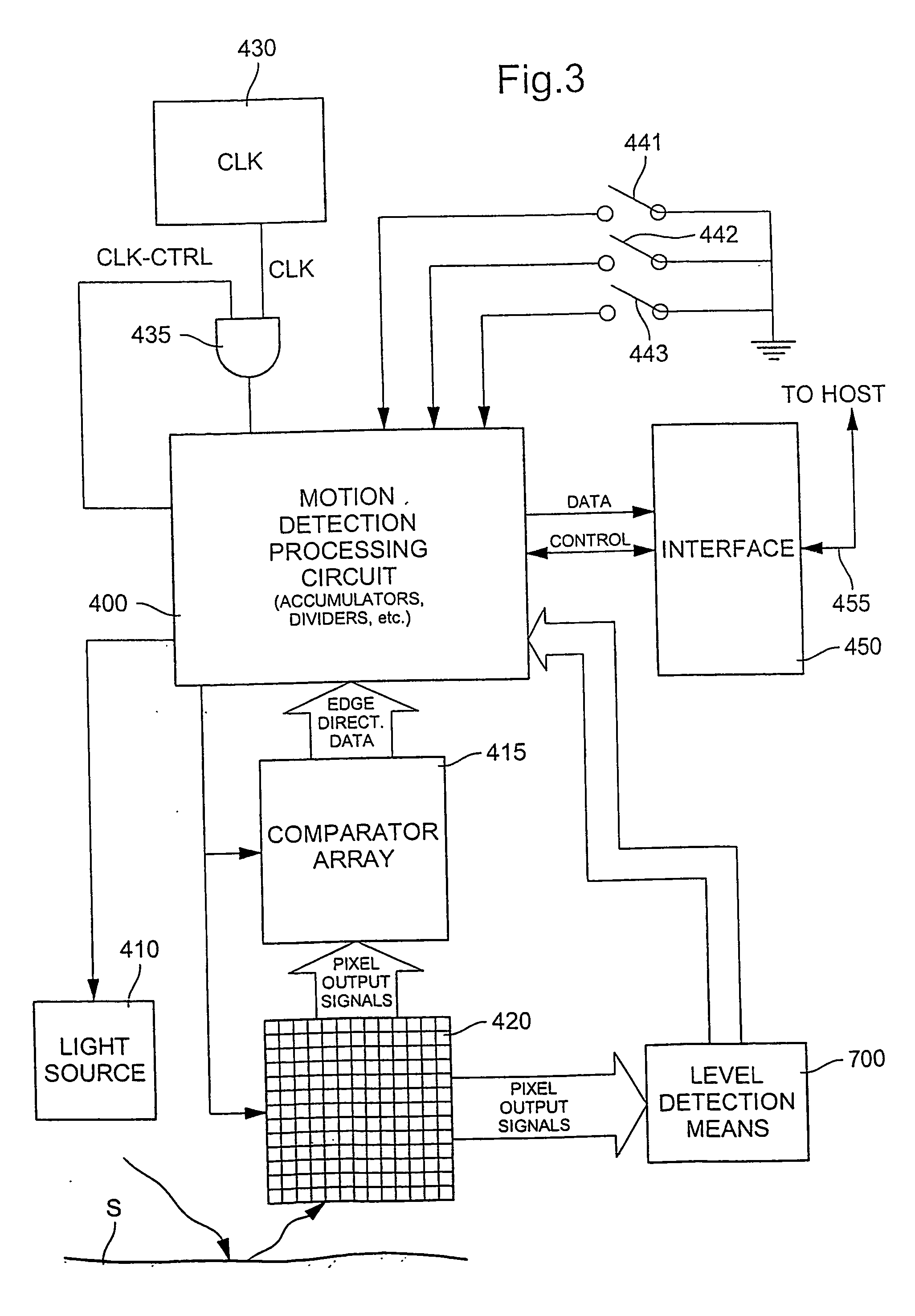
FIG. 3 is a generalized schematic bloc diagram of an optical pointing device in accordance with the present invention. It comprises a photodetector array 420 including a plurality of pixels, this photodetector array 420 being coupled to processing means 400 (or motion detection processing circuit) which consists, in a non limiting manner, of a micro-controller, microprocessor or other adequate logic circuitry for processing the signals outputted by the photodetector array 420. Motion detection processing circuit 400 in particular includes accumulator circuits and other logic circuits for performing mathematical and logic operations as this will be understood hereinafter.

As schematically illustrated in FI...


PUM


Abstract

There is described a method as well as a device for motion detect ion in an optical sensing device, such as an optical mouse. A photodetector array comprising a plurality of pixels is used to detect successive light intensity patterns of an illuminated portion of a surface with respect to which a measurement of relative motion is to be determined. Light intensity between neighbouring pixels is compared in order to determine edge direction data descriptive of light intensity differences between the pixels, such data including (i) a first edge condition, or positive edge, defined as a condition wherein light intensity of a first pixel is less than light intensity of a second pixel, and (ii) a second edge condition, or negative edge, defined as a condition wherein light intensity of the first pixel is greater than light intensity of the second pixel. Through comparison of this edge direction data with edge direction data determined from a previous illumination (or by comparing data extracted from this edge direction data) a measurement of the relative motion of the optical sensing device with respect to the illuminated portion of the surface is determined.

Description

FIELD OF THE INVENTION The present invention generally relates to pointing devices, in particular for controlling the position of a cursor on a screen, such as the display of a personal computer, workstation or other computing devices having a graphic user interface. Such pointing devices may for instance include mice, trackballs and other computer peripherals for controlling the position of a cursor on a display screen. The present invention more particularly relates to the field of optical pointing devices which comprise an optical sensing device including a photodetector array for measuring the varying intensity pattern of a portion of a surface which is illuminated with radiation and for extracting information about the relative motion between the photodetector array and the illuminated portion of the surface. BACKGROUND OF THE INVENTION Optical pointing devices are already known in the art. U.S. Pat. No. 5,288,993, which is incorporated herein by reference, for instance disc...

Claims


Application Information

Patent Timeline
Patent Type & Authority Applications(United States)
IPC IPC(8): G09G5/08
CPCG06F3/0317
Inventor ROTZOLL, ROBERT R.SCOTT, KEVINHAROLD, JAMESAFRIAT, GIL
Owner EM MICROELECTRONIC-MARIN
Why Eureka
Try Eureka