Light irradiating unit and optical fixing unit

a technology of light irradiation and optical fixing, which is applied in the field of light irradiation unit and optical fixing unit, can solve the problems of uneven fixing, and achieve the effect of preventing uneven fixing and preventing variations in the amount of irradiated ligh

Inactive Publication Date: 2005-03-24
FUJIFILM HLDG CORP
View PDF3 Cites 25 Cited by
  • Summary
  • Abstract
  • Description
  • Claims
  • Application Information

AI Technical Summary

Benefits of technology

[0007] An object of the present invention is to provide a light irradiating device which can prevent variations in an amount of irradiated light in a width direction of a sheet-like material.
[0008] Another object of the present invention is to provide a thermal printer which can prevent unevenness in fixing in a width direction of thermosensitive recording paper by using the light irradiating device as an optical fixing unit.
[0010] In a preferred embodiment, an arranging pitch between the light-emitting elements in a first direction of the light-emitting element array, which is approximately parallel to the width direction of the sheet-like material, is lessened from the center area toward the side edge areas of the light-emitting element array. It is also possible to lessen the arranging pitch between the light-emitting elements in a second direction, which is approximately perpendicular to the width direction of the sheet-like material, from the center area toward the side edge areas of the light-emitting element array. It is preferable to provide reflectors on both side edges of the light-emitting element array to reflect light, which is radiated outside of the sheet-like material, toward the sheet-like material.
[0013] According to the present invention, the arranging density of the light-emitting elements increases from the center area to the side edge areas of the light-emitting element array, so that it becomes possible to prevent the variations in the amount of irradiated light caused by radiating part of light to the outside of the sheet-like material. Further, the unevenness in fixing can be prevented in the width direction of the thermosensitive recording paper by using the light irradiating device as the fixing unit for use in the thermal printer.

Problems solved by technology

As a result, the amount of the fixing light irradiated to the record area becomes nonuniform, so there arises a problem in that unevenness in fixing is generated in the width direction of the thermosensitive recording paper.

Method used


Image

  • Light irradiating unit and optical fixing unit
  • Light irradiating unit and optical fixing unit
  • Light irradiating unit and optical fixing unit

Examples


Embodiment Construction

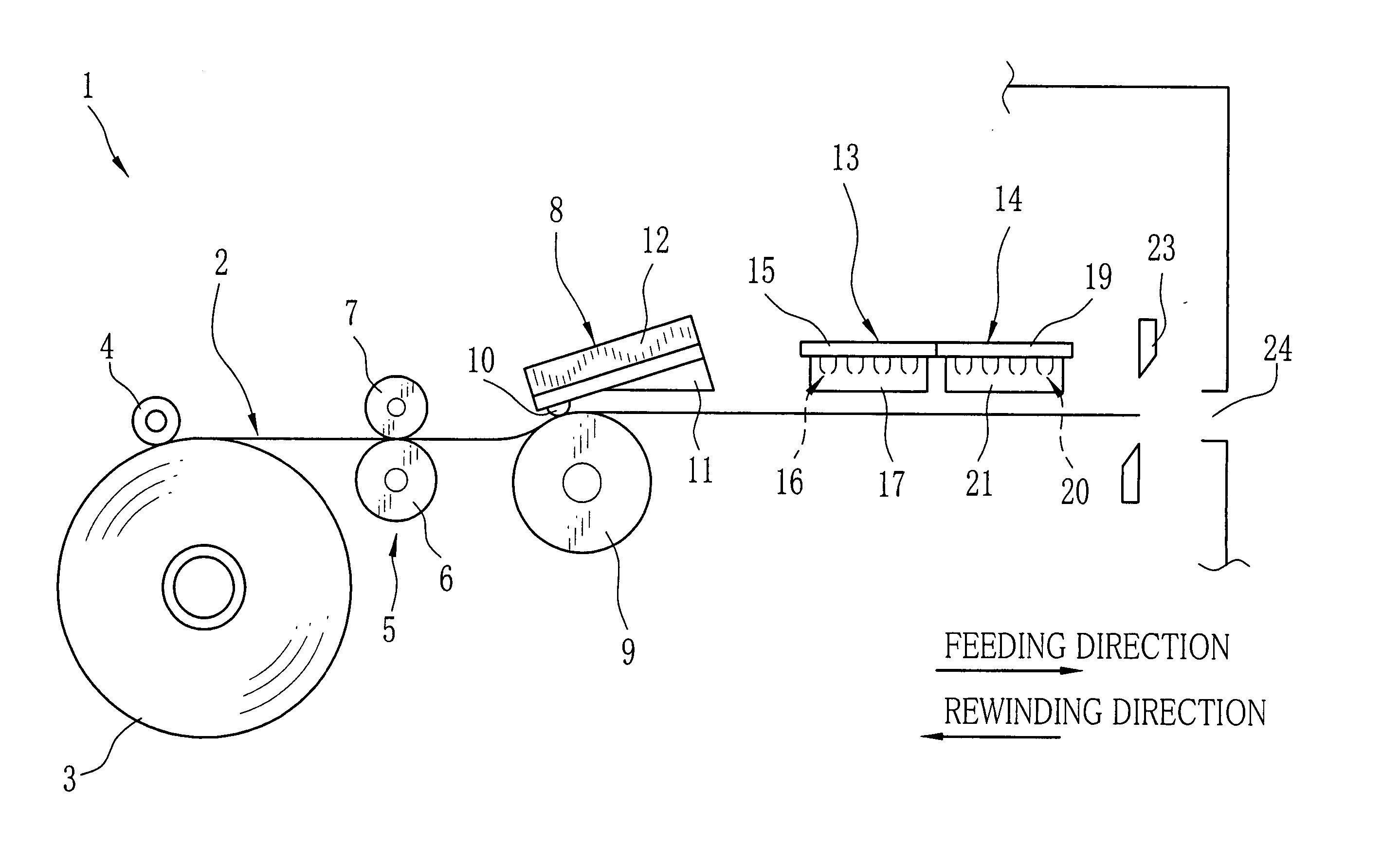
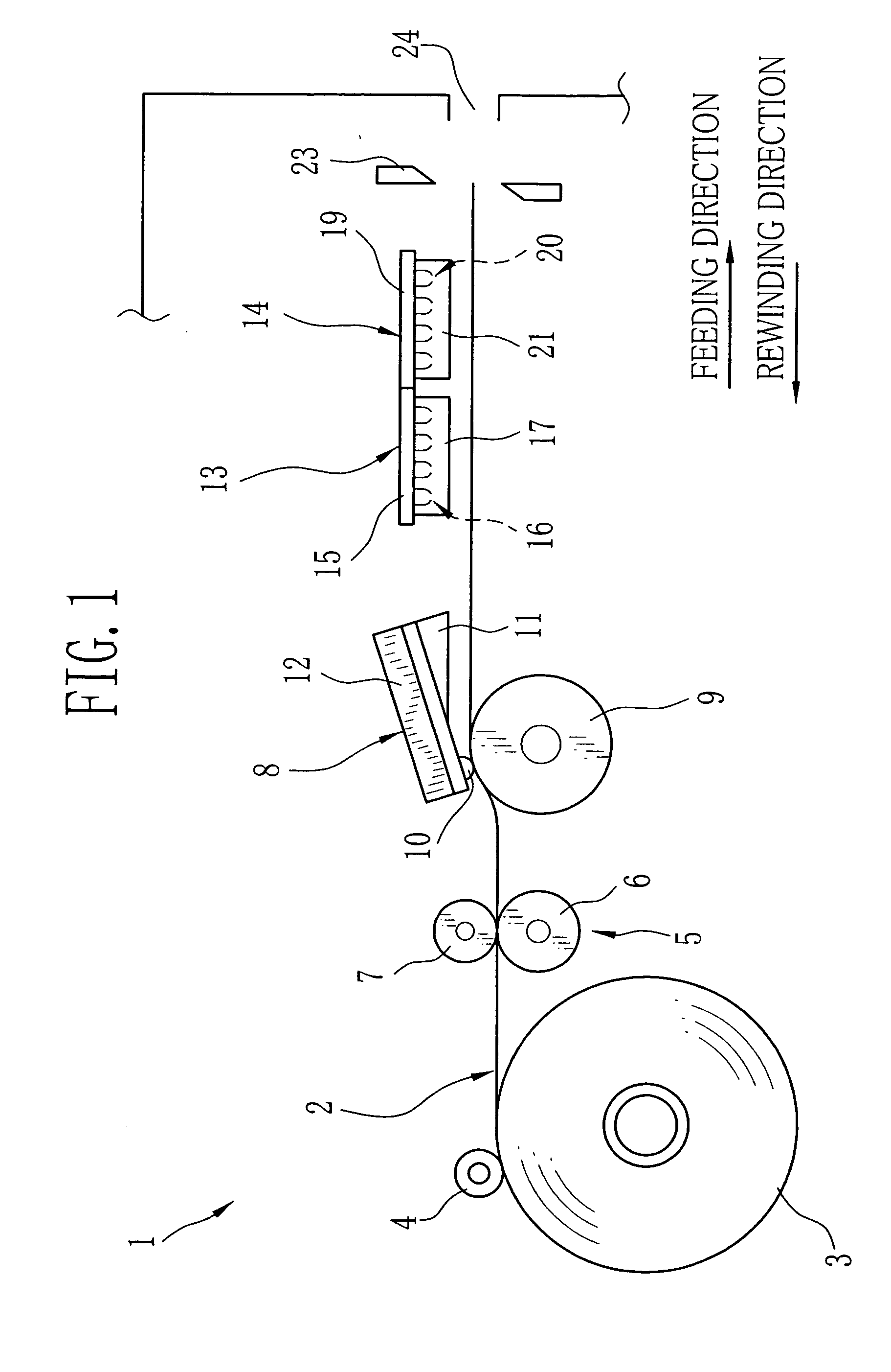
[0020] As shown in FIG. 1, a color thermal printer 1 uses a long strip of color thermosensitive recording paper 2 as a recording medium. The color thermosensitive recording paper 2 is set in the color thermal printer 1 in the form of a recording paper roll 3 which is wound in a roll form.

[0021] A roller 4 comes in contact with an outer periphery of the recording paper roll 3, and is driven by a feeding motor (not shown). When the roller 4 is rotated in a counterclockwise direction in a drawing, the recording paper roll 3 is rotated in a clockwise direction in the drawing, so that the color thermosensitive recording paper 2 is advanced from the recording paper roll 3. On the contrary, when the roller 4 is rotated in the clockwise direction in the drawing, the recording paper roll 3 is rotated in the counterclockwise direction in the drawing, so that the color thermosensitive recording paper 2 is rewound around the recording paper roll 3.

[0022] A feeding roller pair 5 is disposed in...


PUM


Abstract

A width of an LED array in a scanning direction is determined in accordance with a width of thermosensitive recording paper. A plurality of LEDs is arranged in the LED array in such a way that an arranging pitch between the LEDs are lessened from a center area toward side edge areas of the LED array. Thus, an arranging density of the LEDs increases from the center area toward the side edge areas of the LED array, so that radiated fixing light becomes uniform in a width direction of the thermosensitive recording paper. As a result, unevenness in fixing is prevented. Further, irradiation efficiency in the side edge areas of the LED array is improved by providing reflectors on both side edges of the LED array. Accordingly, the unevenness in fixing is prevented more efficiently.

Description

BACKGROUND OF THE INVENTION [0001] 1. Field of the Invention [0002] The present invention relates to a light irradiating unit, and an optical fixing unit provided in a thermal printer. [0003] 2. Background Arts [0004] One or more optical fixing units, which fix images by irradiating fixing light to thermally recorded thermosensitive recording paper, are provided as light irradiating units in a thermal printer. [0005] An optical fixing unit, which uses a light-emitting element array aligned with a plurality of light-emitting elements as a fixing light source, is suggested. (For instance, see Japanese Patent Laid-Open Publication No. 11-260122.) A lengthwise direction of the light-emitting element array is placed along a width direction of the thermosensitive recording paper. A length of the light-emitting element array is determined in accordance with a width of the thermosensitive recording paper. Optical fixing is performed by, for instance, irradiating the fixing light to a whole ...

Claims


Application Information

Patent Timeline
Patent Type & Authority Applications(United States)
IPC IPC(8): B41J11/00B41J2/32
CPCB41J2/45B41J11/002B41J2/4753B41J11/00214B41J11/00218
Inventor TAKI, TOMOKOMIZUYOSHI, AKIRA
Owner FUJIFILM HLDG CORP
Why Eureka
Try Eureka