
Laminated retardation layer, its fabrication process, and liquid crystal display incorporating the same

a technology of retardation layer and liquid crystal display, which is applied in the direction of instruments, polarising elements, optics, etc., can solve the problems of reducing the display contrast, affecting the display quality, and rendering the above-mentioned low contrast and interference variation problems even more noticeable, so as to improve the viewing angle characteristics and high color reproducibility

Inactive Publication Date: 2005-03-24
DAI NIPPON PRINTING CO LTD
View PDF6 Cites 48 Cited by
  • Summary
  • Abstract
  • Description
  • Claims
  • Application Information

AI Technical Summary

Benefits of technology

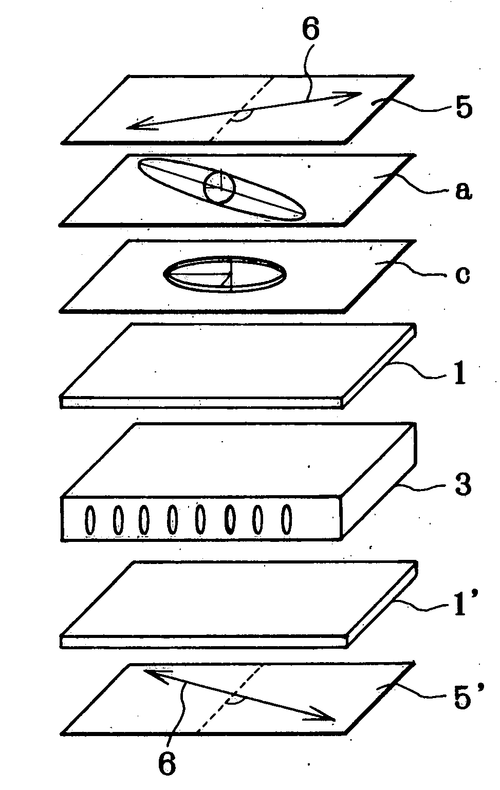
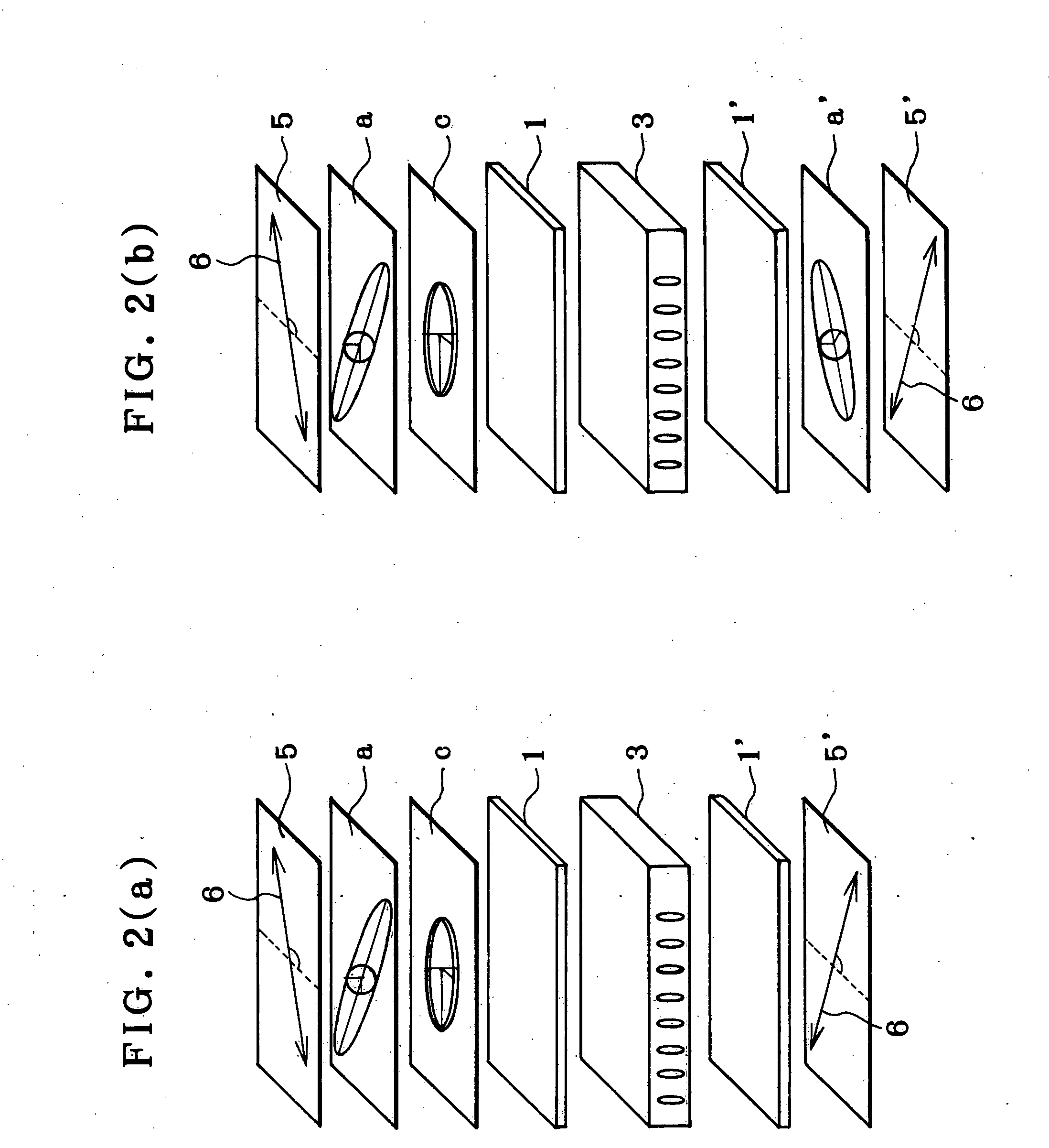
[0043] In view of such problems with the prior art as described above, a primary object of the invention is to provide a liquid crystal display that incorporates a laminated retardation layer comprising a combination of a negative C-plate having a specific chromatic dispersion and a positive A-plate having a specific chromatic dispersion, used to improve the viewing angle characteristics thereof, thereby presenting high-contrast images with high color reproducibility yet with neither interference variations nor color shifts.
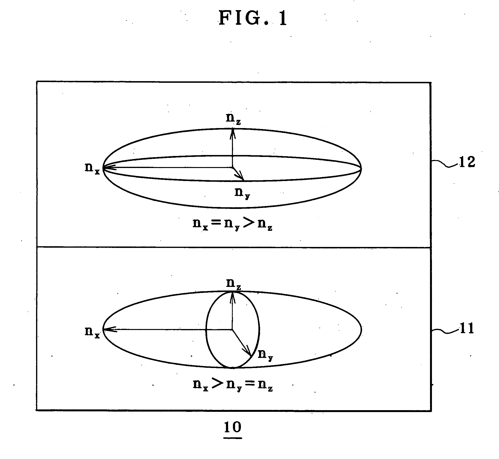
[0050] As described above, the present invention provides a laminated retardation layer obtained by lamination of a retardation layer having positive index anisotropy and an optical axis in a layer plane and a retardation layer having negative index anisotropy and an optical axis in a normal direction to a layer plane, characterized in that a stretched polymer film having inverse chromatic dispersion that causes retardation defined by an optical path difference between extraordinary light and ordinary light to become small as wavelength becomes short is used as said retardation layer having positive index anisotropy and an optical axis in a layer plane, and a coating layer having normal chromatic dispersion that causes retardation defined by an optical path difference between extraordinary light and ordinary light to become large as wavelength becomes short is used as said retardation layer having negative index anisotropy and an optical axis in a normal direction to a layer plane. Thus, the present invention can successfully provide a laminated retardation layer dedicated to liquid crystal displays, especially a VA mode liquid crystal display, which is constructed of easy-to-fabricate positive A-plates and negative C-plate without recourse to another film-formation substrate, alignment layer or adhesive layer and enables viewing angle characteristics to be improved with high contrast yet with neither color shifts nor inference variations.

Problems solved by technology

A problem with LCDs here is that their viewing angle is narrow for two possible reasons; when a VA (vertical alignment) mode LCD is viewed from an oblique direction, the isotropy of liquid crystal molecules goes out of order, causing light that, by definition, is to be linearly transmitted as such, to be converted to elliptically polarized light, and given crossed Nicols sheet polarizers located on both sides of a liquid cell, they appear to go out of crossed alignment upon viewing from an oblique direction.
As a result, there are leakages of light out of pixels that are originally designed for black display, which may otherwise flip over contrast, rendering proper display impossible.
However, the tackifier used to this end is different in the index of refraction than the sheet polarizers and retardation layers, offering problems in that light is reflected at their interfaces, causing the contrast of images on display to become generally low and interference variations.
Especially when the negative C-plate and positive A-plate are located on both sides of a liquid crystal cell in accordance with non-patent publication 1, some more index interfaces add up, rendering the aforesaid low-contrast and interference variation problems even more noticeable.
However, there is still a lot of uncertainty about what type film is to be used as the negative C-plate for elimination of the problem resulting from the fact that the isotropy of liquid crystal molecules in the liquid crystal cell goes out of order upon viewing from an oblique direction; there is still a possibility that color shifts may remain uncorrected.

Method used


Image

  • Laminated retardation layer, its fabrication process, and liquid crystal display incorporating the same
  • Laminated retardation layer, its fabrication process, and liquid crystal display incorporating the same
  • Laminated retardation layer, its fabrication process, and liquid crystal display incorporating the same

Examples


Embodiment Construction

[0061] Before giving an explanation of the laminated retardation layer according to the invention, an account is given of a retardation layer. In the invention, two kinds of retardation layers or a positive uniaxial retardation layer having an optical axis in a layer plane and a negative uniaxial retardation layer having an optical axis in a normal direction to a layer plane are used.

[0062] Two such retardation layers are now explained with reference to FIGS. 7(a) and 7(b). As shown, a z-axis is defined by a normal direction to a layer plane S, x- and y-axes are defined by orthogonal directions in the layer plane S, and refractive indices of the layer in the x-, y- and z-axis directions are indicated at nx, ny and nz. As shown in FIG. 7(a), a retardation layer that satisfies the relation of nx>ny=nz provides a retardation layer having an optically positive uniaxial property in the layer plane S, and will be referred to as a positive A-plate. As shown in FIG. 7(b), a retardation lay...


PUM

PropertyMeasurementUnit
thicknessaaaaaaaaaa
reflection wavelengthaaaaaaaaaa

Abstract

The invention relates to a liquid crystal display that incorporates a laminated retardation layer 10 comprising a combination of a negative C-plate having a specific chromatic dispersion and a positive A-plate having a specific chromatic dispersion, used to improve the viewing angle characteristics thereof, thereby presenting high-contrast images with high color reproducibility yet with neither interference variations nor color shifts. The laminated retardation layer 10 is obtained by lamination of a retardation layer 11 having positive index anisotropy and an optical axis in a layer plane and a retardation layer 12 having negative index anisotropy and an optical axis in a normal direction to a layer plane. A stretched polymer film having inverse chromatic dispersion that causes retardation defined by an optical path difference between extraordinary light and ordinary light to become small as wavelength becomes short is used as the retardation layer 11 having positive index anisotropy and an optical axis in a layer plane, and a coating layer having normal chromatic dispersion that causes retardation defined by an optical path difference between extraordinary light and ordinary light to become large as wavelength becomes short is used as the retardation layer 12 having negative index anisotropy and an optical axis in a normal direction to a layer plane.

Description

BACKGROUND OF THE INVENTION [0001] The present invention relates generally to a laminated retardation layer, its fabrication process, and a liquid crystal display incorporating the same, and more particularly, a retardation layer for making the viewing angle of a liquid crystal display larger and improving color reproducibility, its fabrication process, and a liquid crystal display that incorporates the same. [0002] Featuring slim size, low weight, low power consumption and flickerless, color liquid crystal displays (liquid crystal displays referred hereinafter to as LCDs for short) have increasingly expanded market, especially in the form of notebook computers. As part of PC-dedicated displays, there is now a growing demand for desktop monitors that are by far larger than notebook computers. Further, LCDs are finding applications for just only PCs but also TVs for which CRTs have so far been primarily used. [0003] A problem with LCDs here is that their viewing angle is narrow for t...

Claims


Application Information

Patent Timeline
Patent Type & Authority Applications(United States)
IPC IPC(8): G02B5/30G02F1/13363
CPCG02B5/3016G02F1/133634G02B5/3083
Inventor KASHIMA, KEIJI
Owner DAI NIPPON PRINTING CO LTD
Learn More