Electrical apparatus and a limiting method

a technology of limiting method and electric apparatus, which is applied in the direction of electronic switching, pulse technique, and arrangements responsive to excess voltage, can solve the problems of reducing the service life of the diode, so as to reduce the loss, reduce the loss, and protect the semiconductor device from high peak voltage

Inactive Publication Date: 2005-03-24
ABB POWER GRIDS SWITZERLAND AG
View PDF5 Cites 9 Cited by
  • Summary
  • Abstract
  • Description
  • Claims
  • Application Information

AI Technical Summary

Benefits of technology

According to another preferred embodiment of the invention the apparatus is adapted to limit the peak voltage across the rectifying members of a current valve with a series connection of semiconductor devices and rectifying members connected in anti-parallel therewith, and the apparatus comprises said means adapted to individually control the semiconductor device belonging to each individual rectifying member to turn on at least slightly when the rectifying member is turning off. By the fact that the invention in this way enables an active control of the peak voltage at each position and the peak voltage is not controlled by for example stray capacitances to ground, by differences in the maximum reverse current through the diodes or by tolerances of the snubber capacitors, a protection of each semiconductor device against high peak voltages may reliably and safely be obtained. Furthermore, the losses get lower than when using the RC- or RCD-circuits already known as snubber members, since in a RC-circuit the capacitor is charged and the energy is converted into heat each time, while in a RCD-circuit at such a series connection differently much energy will be stored in the capacitors for different rectifying members, and this energ

Problems solved by technology

If no apparatus of the type defined in the introduction would be used for limiting this peak voltage this inductive over-voltage would destroy the diode.
However, a disadvantage of this solution is that comparatively large RC-snubber members, with a capacitor having a capacitance in the region of μF, are required, which results in considerable costs.
Furthermore, the peak voltage value when commutating the diode 23 to turn off will still be comparatively high and the losses create

Method used


Image

  • Electrical apparatus and a limiting method
  • Electrical apparatus and a limiting method
  • Electrical apparatus and a limiting method

Examples


Embodiment Construction

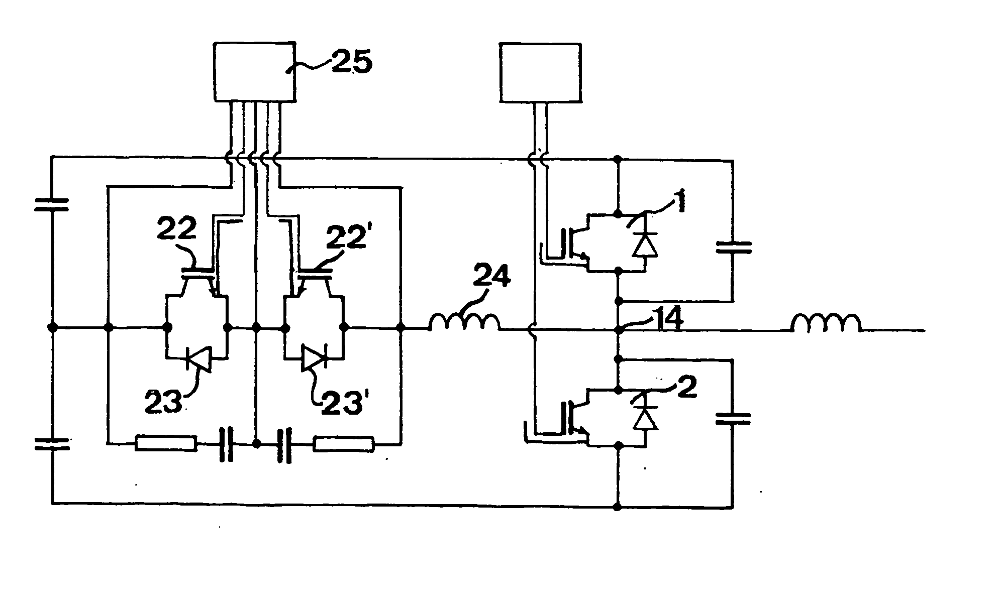
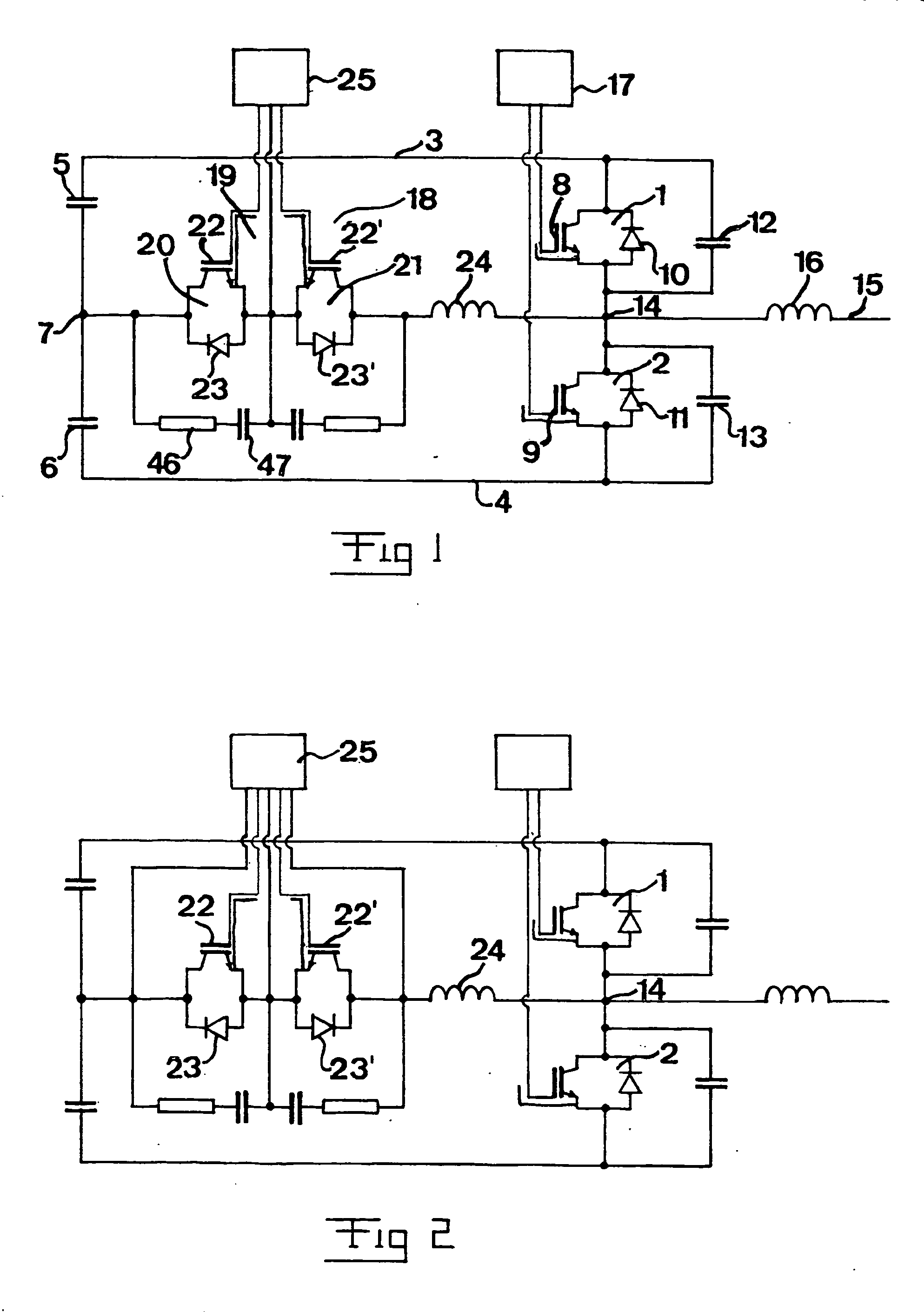
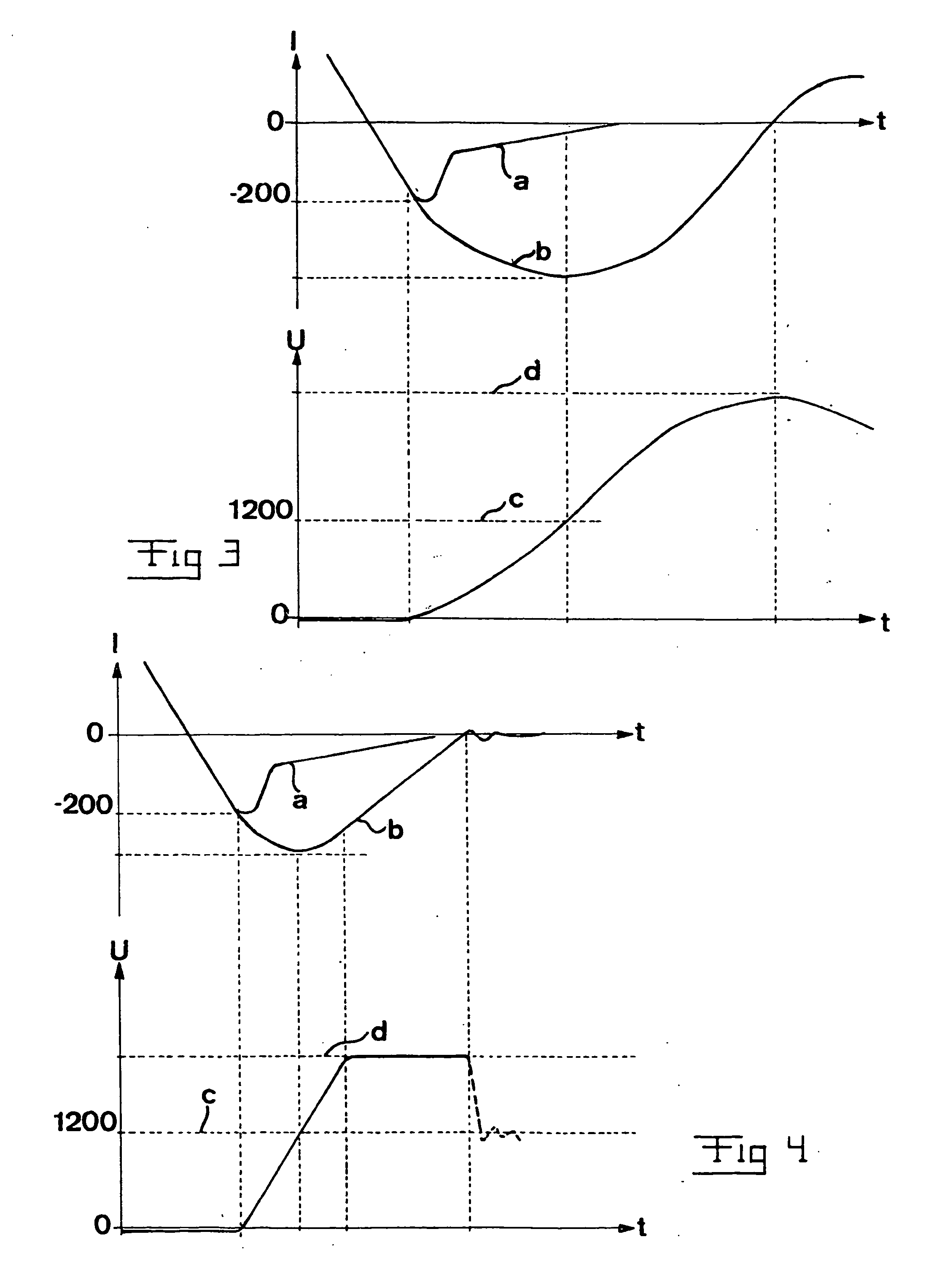
The basic idea of the invention has very schematically been shown in FIG. 2 by showing there how the second control arrangement 25 is modified and connected in another way than the control arrangement 25 of the converter according to FIG. 1, more exactly in such a way that it comprises means adapted to control the semiconductor device connected in anti-parallel with the rectifying member 23 or 23′ when this is turning off so that the conductivity increases. What this means in practice is shown in the diagram in FIG. 4, which corresponds to the diagram according to FIG. 3. The following data and properties may be valid for this: We assume that Udc=1200 volts, the maximum reverse current in the diode 23 Irm=200 A, the inductance of the inductor 24 L=8 μH (di / dt=−1200 V / 8 μH=−150 A / μs) and the diode turns rapidly off. The IGBT 22 in anti-parallel will limit dVce / dt (Vce=the collector emitter voltage of the IGBT) to a certain pre-determined value, such as for example 1 kV / μs. A somewha...


PUM


Abstract

An electrical apparatus for limiting the peak voltage across a recttifying member (23) of a current valve arranged in a circuit having a substantial inductance (24) and having at least one controllable semiconductor device (22) and at least one said rectifying member (23) connected in anti-parallel therewith when the rectifying member is turning off, comprises means (28, 29) adapted to control the semiconductor device so as to increase the conductivity thereof during turning off of the rectifying member.

Description

The present invention relates to an electrical apparatus for limiting the peak voltage across a rectifying member of a current valve arranged in a circuit having a substantial inductance and having at least one controllable semiconductor device and at least one said rectifying member connected in anti-parallel therewith when the rectifying member is turning off. Such a rectifying member is usually, although not necessarily, a diode, so that hereinafter by way of example and for simplification, but not at all by way of limitation, the word diode will be used. Furthermore, the word IGBT will hereinafter by way of example, but not by way of limitation, be used for said controllable semiconductor device. Furthermore, the invention comprises an electrical apparatus for such a peak voltage limitation across such a diode when it is turning off in all types of circuits having a substantial, i.e. comparatively high, inductance creating a heavy inductive over-voltage when the diode is turn...

Claims


Application Information

Patent Timeline
IPC IPC(8): H02M3/28H03K17/082
CPCH03K17/0828H02M2007/4811H02M7/4811
Inventor LUNDBERG, PETERBIJLENGA, BOAL-HOSINI, FALAHJOHANSSON, NICKLAS
Owner ABB POWER GRIDS SWITZERLAND AG
Why Eureka
Try Eureka