Circulating fluidized bed boiler

a fluidized bed and boiler technology, applied in the direction of combustion types, furnaces, steam generation using hot heat carriers, etc., can solve the problems of high temperature corrosion by corroding halogen gas, and achieve the effect of prolonging the service life of the in-bed tub

Inactive Publication Date: 2005-03-24
IHI CORP
View PDF8 Cites 11 Cited by
  • Summary
  • Abstract
  • Description
  • Claims
  • Application Information

AI Technical Summary

Benefits of technology

[0014] The circulating fluidized bed boiler of the present invention provides a furnace which combusts a fuel which is fluidized together with a bed material, a cyclone dust collector into which an flue gas which is generated by the combustion in the furnace is introduced and which catches particles in the flue gas, a seal box into which most of the particles which are caught by the cyclone dust collector are introduced, an external heat exchanger which is arranged in a downstream side of the seal box. The above fluidized bed boiler further provides a separation loop, in the seal box, upstream of heat exchanger 6, which separates corrosive components from the particles so as not to introduce the corrosive components to the external heat exchanger.
[0015] According to the above circulating fluidized bed boiler, the fuel which is fluidized together with the bed material combusts and the particles which are blown upward with the flue gas which is generated by this combustion are caught in the cyclone dust collector and are introduced to the separation loop. The separation loop combusts unburned particles which are contained in the combustible particles by the fluidizing air so as to separate the corrosive components with the particles and the off gas in the seal box is introduced to the furnace through a duct which is arranged above the seal box prior to being introduced to the external heat exchanger; therefore it is possible to solve the corrosion problem on the high temperature metal tube due to melted salts. Because the unburned particles are thus combusted by the separation loop, and an amount of the unburned particles flowing into the external heat exchanger in which the in-bed tube is arranged is minimized, the service life of the in-bed tube is extended.

Problems solved by technology

Further, a high temperature corrosion by corrosive halogen gas, e.g., chlorine gas, which is generated during the above combustion occurs in the heat exchanger 6.

Method used


Image

  • Circulating fluidized bed boiler
  • Circulating fluidized bed boiler
  • Circulating fluidized bed boiler

Examples


first embodiment

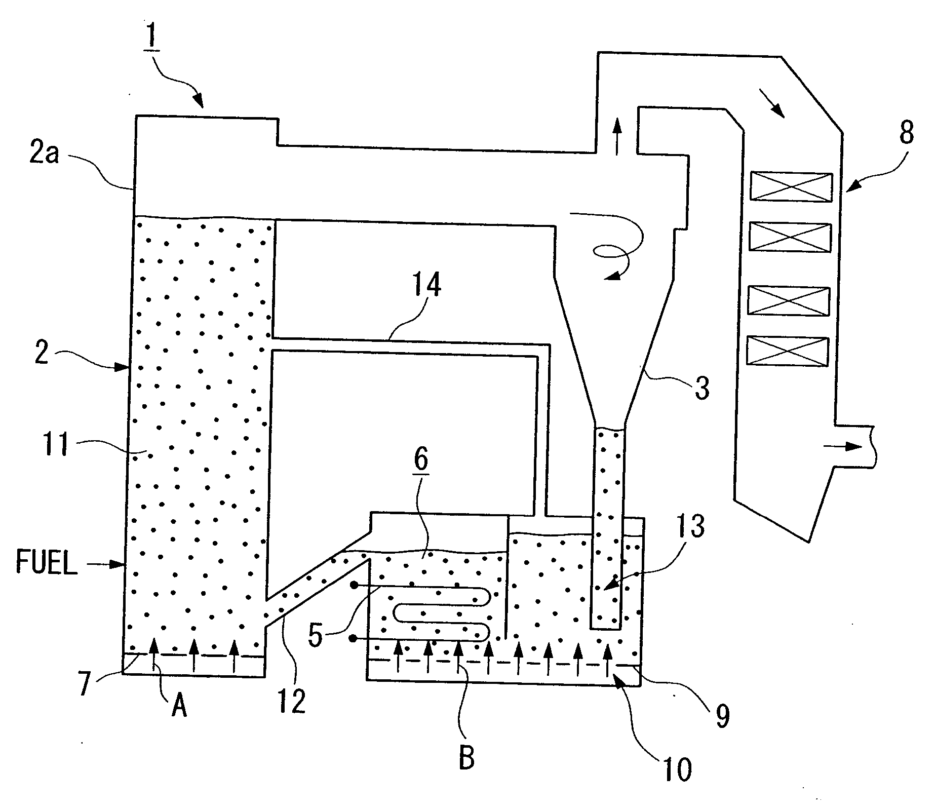
[0029] The fluidized bed boiler 1 of the first embodiment comprises a furnace 2, a cyclone dust collector 3 into which an flue gas generated by a combustion in the furnace 2 and which catches particles which are contained in the flue gas, a separation loop into which the particles which are caught by the cyclone dust collector 3 are introduced, and an external heat exchanger 6 which is integrated with the separation loop.

[0030] The furnace 2 comprises the water cooled furnace wall 2a in a bottom part of which the air distribution nozzle 7, which introduces fluidizing air A into the furnace 2, is arranged. The cyclone dust collector 3 is connected with an upper part of the furnace 2 and an upper part of the cyclone dust collector 3 is connected with a heat recovery area 8 into which the flue gas is generated by the combustion in the furnace 2. A bottom part of the cyclone dust collector 3 is connected with a separation loop 13 into which the particles which are caught by the cyclone ...

second embodiment

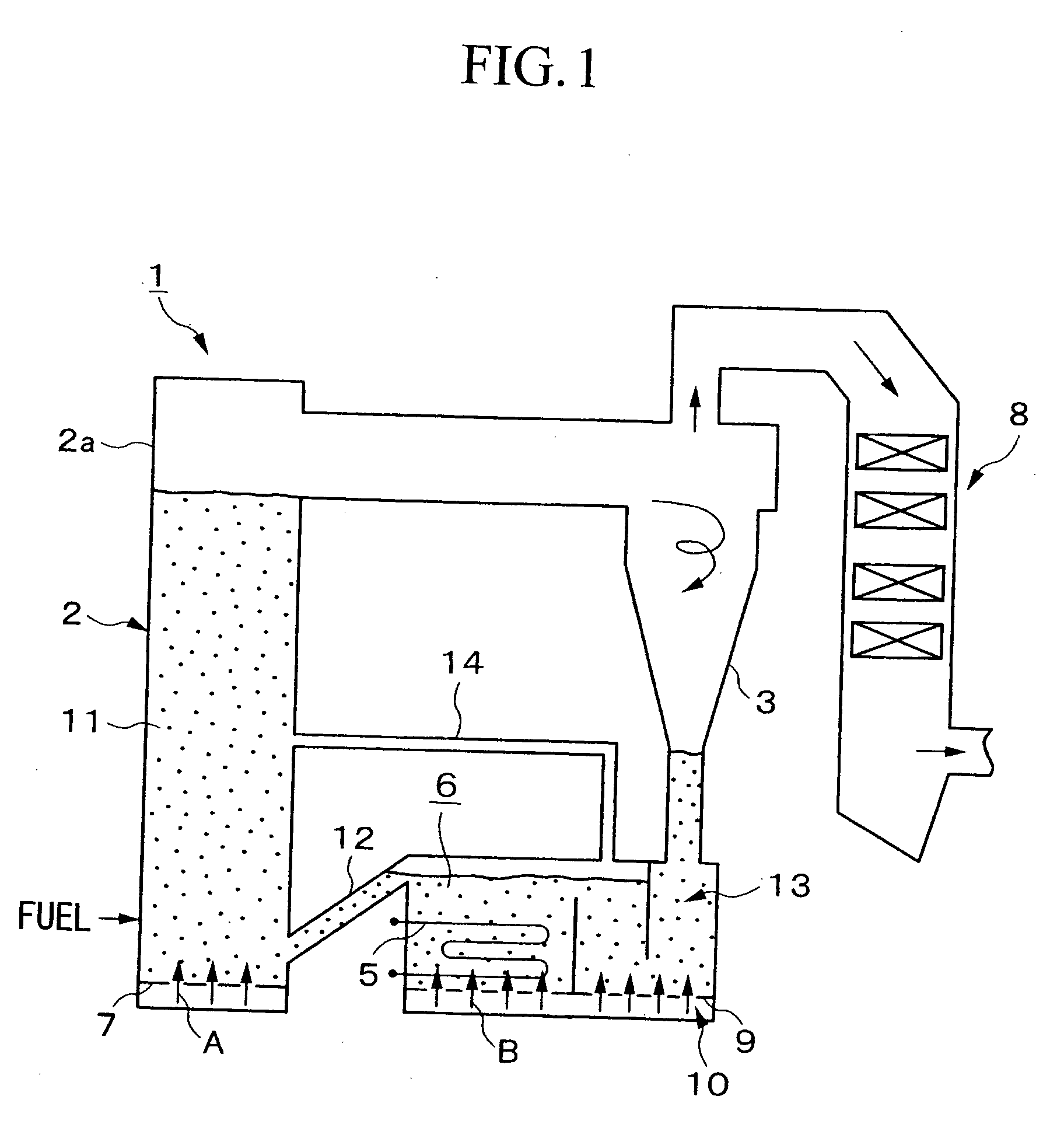
[0040]FIG. 2 shows the present invention. In FIG. 2, components which are similar to the components of FIG. 1 are indicated by the same numerals as in FIG. 1.

[0041] The common construction of the fluidized bed boiler 1 of the second embodiment is similar to that of the first embodiment in FIG. 1. In this embodiment, the heat exchanger 6 is connected with the seal box 4 at a bottom part in order to introduce the particles.

third embodiment

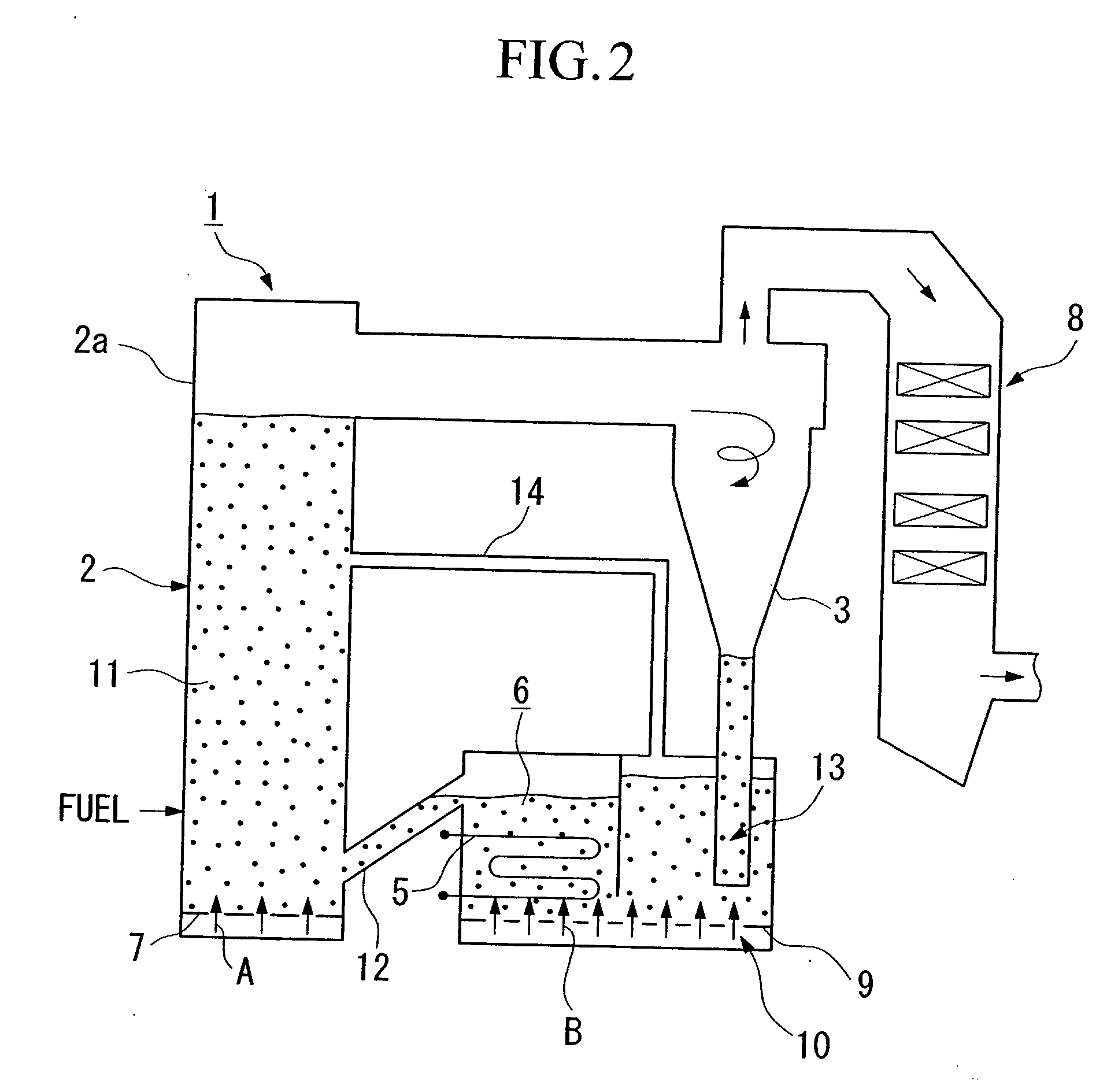
[0042]FIG. 3 shows the present invention. In FIG. 3, components which are similar to the components of FIG. 1 are indicated by the same numerals as in FIG. 1.

[0043] The common construction of the fluidized bed boiler 1 of the third embodiment is similar to that of the first embodiment in FIG. 1. The aspect of the third embodiment is that a sealing loop 15, through which the circulating particles return to the bottom of the furnace 2, is arranged in a branch path which branches from the bottom of the cyclone dust collector 3.

[0044] The fluidized bed boiler 1 of the third embodiment can control the temperature of the furnace 2 during the combustion by adjusting the ratio of the amount of particles which pass through the sealing loop 15 and return to the furnace 2 to another particles which pass the external heat exchanger 6 and return to the furnace 2. Other actions of the fluidized bed boiler of the third embodiment is similar to those of the first embodiment.


PUM


Abstract

A circulating fluidized bed boiler has reduced corrosion in the exchanging tube in an external heat exchanger. The circulating fluidized bed boiler has a furnace which combusts a fuel which is fluidized together with a bed material, a cyclone dust collector into which an flue gas which is generated by the combustion in the furnace is introduced and which catches particles in the flue gas, a separation loop, in a seal box, which separates corrosive components from the particles so as not to introduce the corrosive components to the external heat exchanger which is arranged downstream of the seal box.

Description

CROSS-REFERENCE TO RELATED APPLICATIONS [0001] This is a continuation of U.S. patent application Ser. No. 10 / 291,896, filed Nov. 8, 2002 in the name Shuzo WATANABE and entitled CIRCULATING FLUIDIZED BED BOILER.BACKGROUND OF THE INVENTION [0002] 1. Field of the Invention [0003] The invention relates to a circulating fluidized bed boiler for combusting wastes or solid fuels which contain corrosive components such as chlorine, by feeding the wastes or the solid fuels together into circulating fluidized bed in a furnace. [0004] 2. Background Art [0005]FIG. 5 shows a construction of a conventional circulating fluidized bed boiler. Generally, the circulating fluidized bed boiler comprises a furnace 2, a cyclone dust collector 3 into which flue gas which is generated by the combustion in the furnace 2 flows and which catches particles which are contained in the flue gas, a seal box 4 into which the particles which are caught by the cyclone dust collector 3 flow and external heat exchanger ...

Claims


Application Information

Patent Timeline
Patent Type & Authority Applications(United States)
IPC IPC(8): F23G5/30F22B1/02F23C10/08F23C10/10F23C10/18F23G5/48
CPCF23C10/10F23C2206/103F23G2203/501F23G5/48F23G5/30F23C10/08
Inventor WATANABE, SHUZO
Owner IHI CORP
Why Eureka
Try Eureka