

Distributed operator cooling system
a distributed operator and cooling system technology, applied in the field of hvac systems, can solve the problems of degrading the cooling capacity of the air being moved, not considered practical in conventional a/c systems, and air conditioning systems for use in agricultural tractors, etc., to reduce the risk of refrigerant contact, and improve the efficiency of the refrigerant cycle
- Summary
- Abstract
- Description
- Claims
- Application Information
AI Technical Summary
Benefits of technology
Problems solved by technology
Method used
Image

Examples
Embodiment Construction
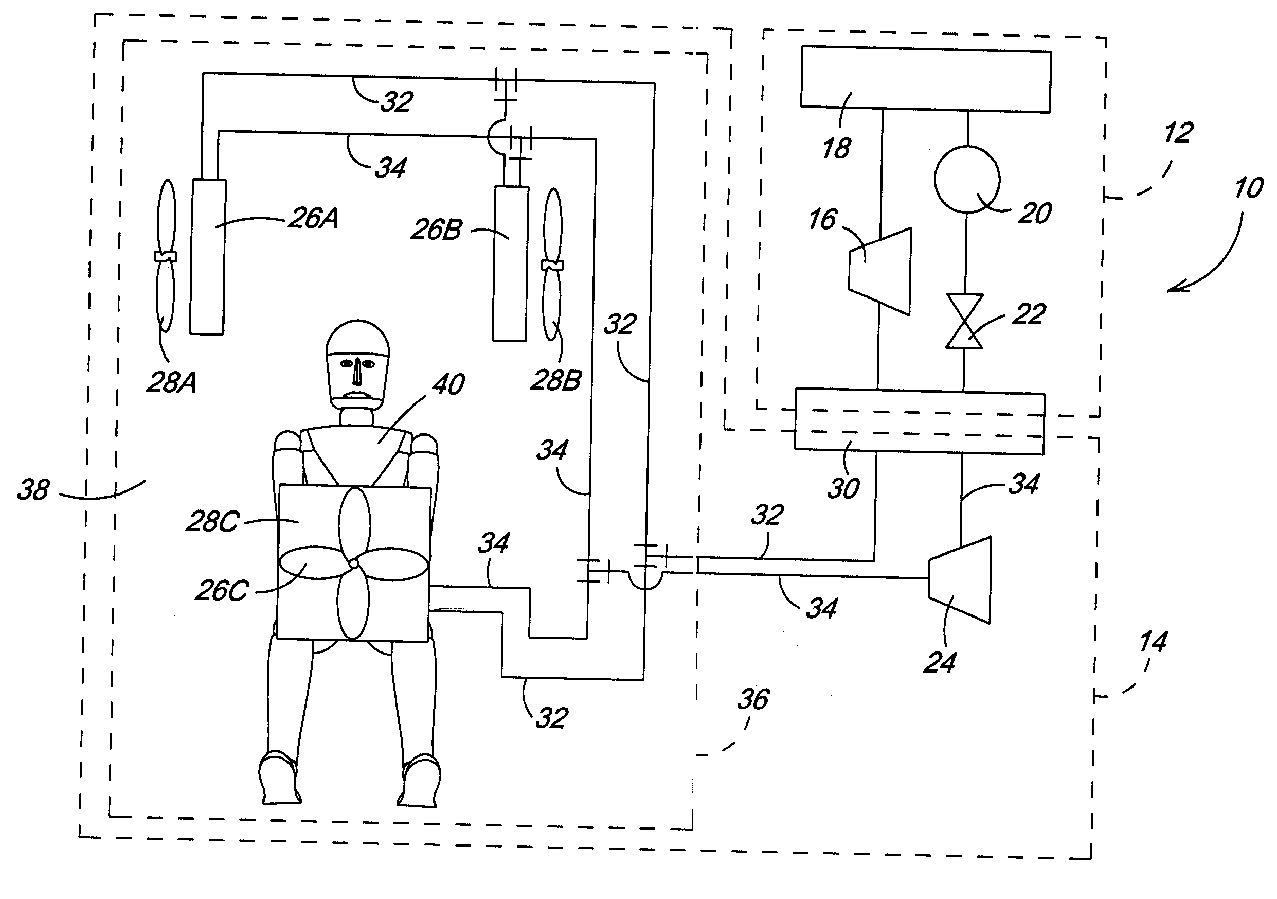
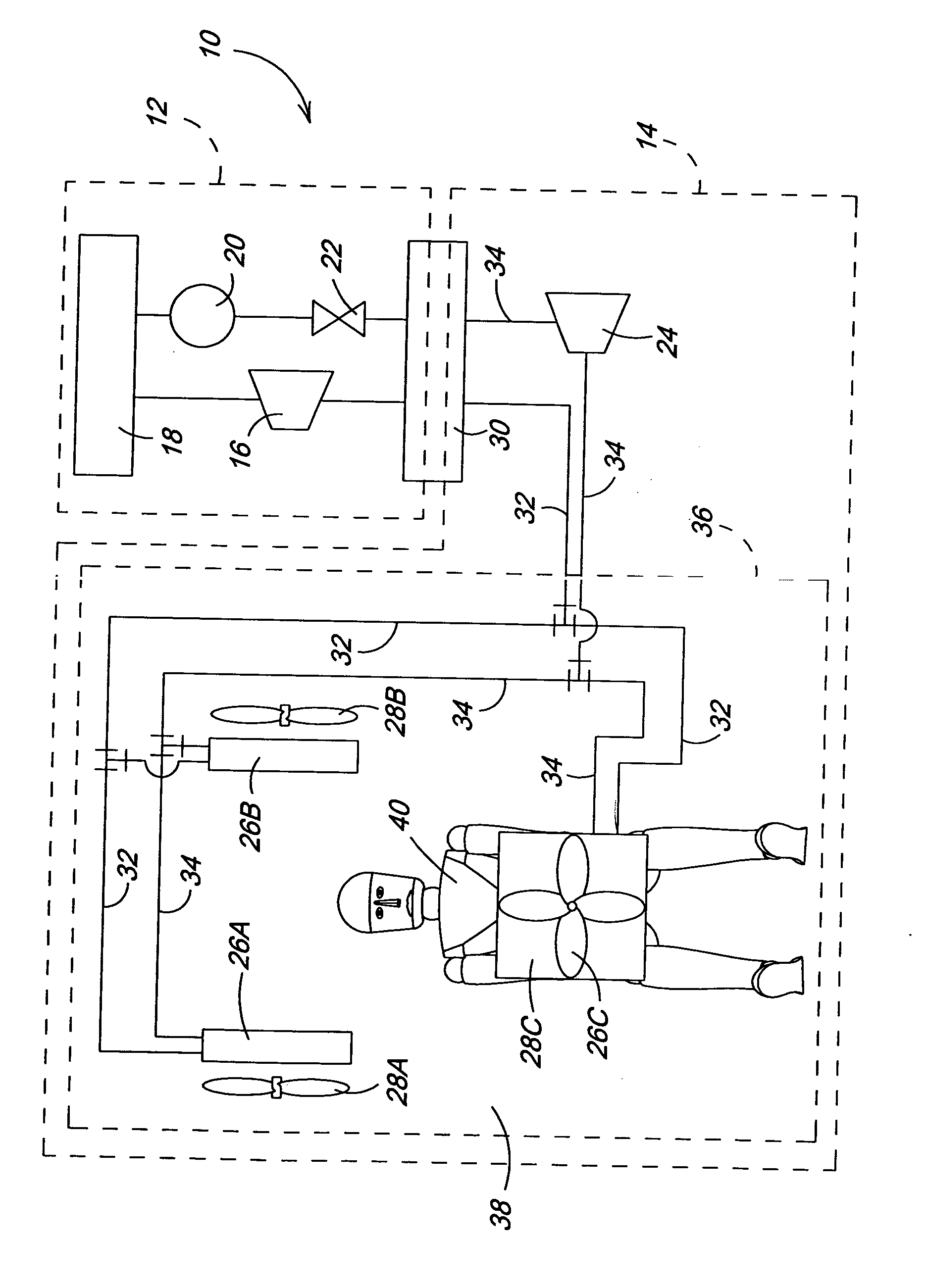
[0014] With reference now to the drawings it can be seen that a distributed operator cooling system for a work vehicle according to the invention is designated generally by the numeral 10. The system 10 generally includes a primary circuit 12 and a secondary loop 14. The primary circuit 12 is a conventional A / C circuit having a compressor 16, a condenser 18, a receiver / dryer 20 and an expansion valve 22. Those having skill in the art will recognize that it is possible to substitute an accumulator and orifice in place of the receiver / dryer and expansion valve illustrated. Such a configuration is not shown in the figures, but it should be understood that the arrangement of components of the primary circuit may necessarily vary from what is shown in the figures if such substitute components are employed. The primary circuit 12 preferably utilizes CO2 or an HC or HFC refrigerant. The secondary loop 14 generally includes a coolant pump 24 and a plurality of coolant-air heat exchangers 26...
PUM
 Abstract
Description
Claims
Application Information