Fluid sensor fixture for dynamic fluid testing

Inactive Publication Date: 2005-03-31
ROCKWELL AUTOMATION TECH
View PDF21 Cites 82 Cited by
  • Summary
  • Abstract
  • Description
  • Claims
  • Application Information

AI Technical Summary

Problems solved by technology

For example, prior to conception of the present invention in situ measurement of oxidation levels of a fluid was ineffective due to a significant amount of time required for chemical reactions re

Method used


Image

  • Fluid sensor fixture for dynamic fluid testing
  • Fluid sensor fixture for dynamic fluid testing
  • Fluid sensor fixture for dynamic fluid testing

Examples


Example

[0037] The present invention is now described with reference to the drawings, wherein like reference numerals are used to refer to like elements throughout. In the following description, for purposes of explanation, numerous specific details are set forth in order to provide a thorough understanding of the present invention. It may be evident, however, that the present invention may be practiced without these specific details. In other instances, well-known structures and devices are shown in block diagram form in order to facilitate describing the present invention.

[0038] As used in this application, the term “computer component” is intended to refer to a computer-related entity, either hardware, a combination of hardware and software, software, or software in execution. For example, a computer component may be, but is not limited to being, a process running on a processor, a processor, an object, an executable, a thread of execution, a program, and / or a computer. By way of illust...


PUM


Abstract

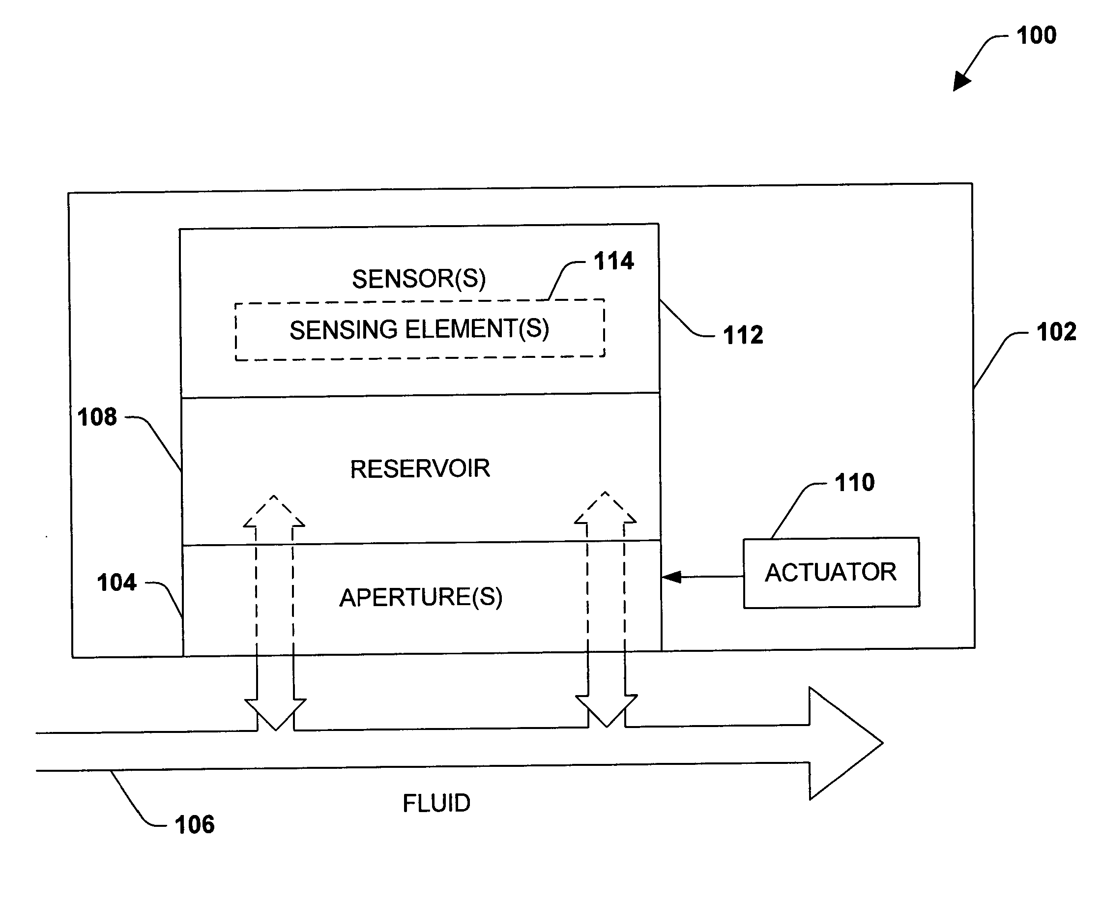
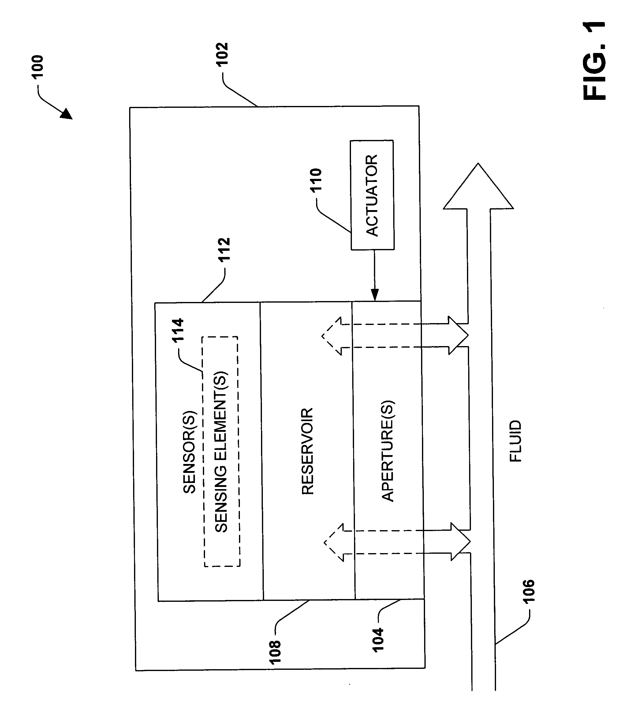
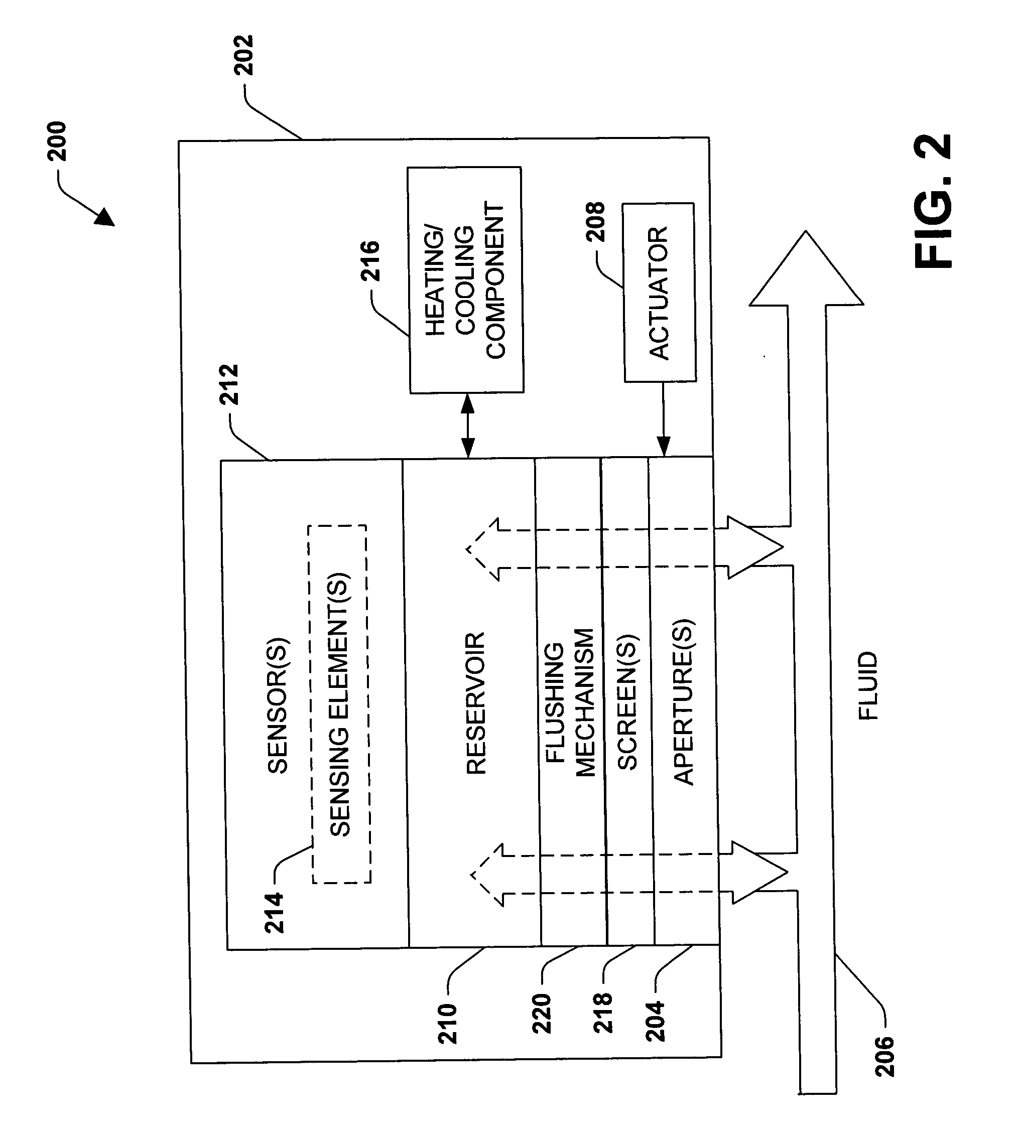
A system that facilitates measurement, analysis, and automatic maintenance of fluid comprises a fluid, and a casing that includes a plurality of apertures is immersed in the fluid. The apertures are opened to permit the fluid to enter the casing and closed to confine a sample of the fluid within the casing. A sensing element within the casing measures at least one parameter of the sample of fluid confined within the casing.

Description

TECHNICAL FIELD [0001] The present invention generally relates to measurement and analysis of multiple parameters of fluids. More particularly, the invention relates to a system and / or methodology that facilitates real-time in situ measurement and analysis of fluids utilized in machinery, as well as to automatically maintaining fluid in machinery. BACKGROUND OF THE INVENTION [0002] Dynamoelectric machines such as motors and generators and other rotating machines such as gears and bearing systems are widely employed in industrial and commercial facilities. These machines are relied upon to operate with minimal attention and provide for long, reliable operation. Many facilities operate several hundred or even thousands of such machines concurrently, several of which are integrated into a large interdependent process or system. Several machines, such as aircraft, land vehicles, and marine systems employ micro-electrical mechanical system (MEMs) sensors to obtain measurements related to...

Claims


Application Information

Patent Timeline
IPC IPC(8): G01N33/28G01N35/10
CPCG01N2035/1062G01N33/2888
Inventor DISCENZO, FREDERICK M.
Owner ROCKWELL AUTOMATION TECH
Why Eureka
Try Eureka