
Methods for cleaning processing chambers

Inactive Publication Date: 2005-03-31
AGERE SYST INC
View PDF6 Cites 15 Cited by
  • Summary
  • Abstract
  • Description
  • Claims
  • Application Information

AI Technical Summary

Benefits of technology

[0007] This invention provides a novel metal etching process and subsequent cleaning process designed for assisting in the removal of sidewall polymers formed in the substrate and of residues formed in the plasma etching chamber. The terms etchant residue, polymer debris and debris are used interchangeably herein. The subject methods diminish wasted production time of cleaning the chamber, as the subject methods allow for more repetitions before having to shutdown the system to perform a wet clean. This invention also provides a cleaner substrate and thus enhances the sidewall polymer removal from the substrate during the post clean process.
[0008] According to a preferred embodiment, the subject invention involves subjecting a plasma chamber containing a wafer to an oxygen-containing gas, such as oxygen (O2), ozone (O3), NO, or NO2, during the dechucking of the wafer. Dechucking, as that term is used in the art, refers to introduction of a gas into the etching chamber following the etching process so as to effect a release of the wafer from a support or chuck. Preferably, the introduction of the oxygen-containing gas is performed during or immediately after a metal etching on the wafer. The metal etching step may comprise subjecting a substrate comprising a metal containing layer thereon with an energized gas such as Cl2, BCl3, or CHF3, or mixtures thereof. The method of introducing oxygen-containing gas following the etching steps provides improved cleaning of the substrate polymers because they can clean the polymer residue at lower temperatures (e.g. 25C vs. 240C) before the polymer is hardened by extra crosslinks produced by high temperatures in the strip chamber. Furthermore, contrary to conventional belief, the inventors have discovered that using the foregoing metal etching gas(es) followed by or in conjunction with an oxygen-containing gas does not corrode the metal on the substrate. Corrosion has been shown to occur when using oxygen-containing gases during the metal etching stage when N2 instead of CHF3 gas is used in the reactive gas mixture.
[0009] The invention also provides enhanced cleaning of the plasma etching chamber, especially of the plasma etching surfaces in close proximity to the substrate, i.e. plasma focus ring. By using the O2 dechuck step proposed by this invention in combination with an in-situ non-product wafer plasma clean, the life of the plasma chamber (time between wet cleans) can be increased by 10 to 20% without any production loss time. This is accomplished by optimizing the in-situ waferless plasma clean to clean plasma chamber surfaces that are far from the substrate (top chamber dome) by manipulating the chamber pressure. In typical non-product wafer in-situ plasma cleans there are two main steps: one aimed to clean plasma chamber regions that are far away from the product wafer and another aimed to clean plasma chamber regions that are close to the product wafer. This invention already provides the means to clean the plasma chamber regions close to the product wafer such that the latter part of the non-product wafer in-situ plasma clean is not necessary.

Problems solved by technology

Corrosion has been shown to occur when using oxygen-containing gases during the metal etching stage when N2 instead of CHF3 gas is used in the reactive gas mixture.

Method used


Image

  • Methods for cleaning processing chambers
  • Methods for cleaning processing chambers

Examples


Embodiment Construction

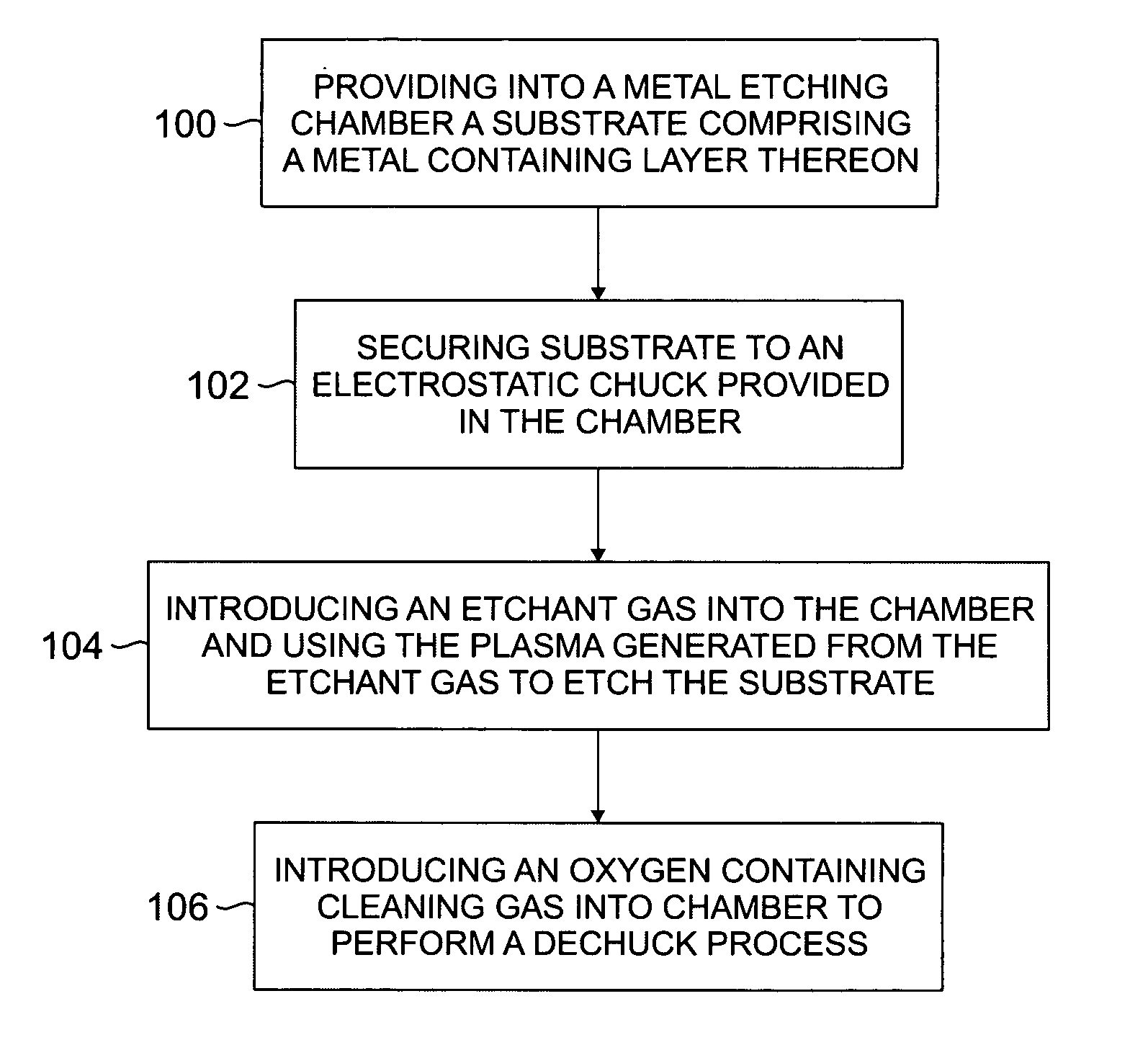
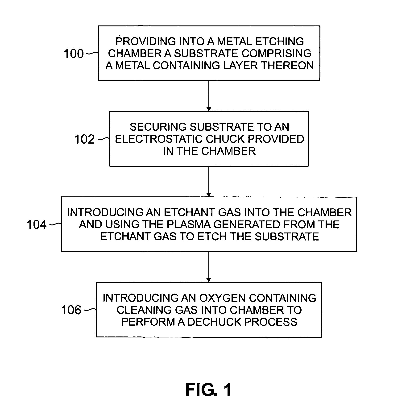
[0013] The present invention provides a etchant residue cleaning method, wherein the residue resulting from a metal process is softened, burnt and even removed. The processing time is thus reduced to provide a consistent yield. According to an exemplary embodiment, the subject methods are applied during or after a metal etching process that uses Cl2, BCl3, and CHF3, as the etchant gas. An etchant gas mixture is introduced into a metal etching chamber containing a substrate comprising a metal containing layer to generate plasma for performing the etchant process. The metal containing layer may comprise Aluminum, or Copper, or both, and / or other metals that are layered on a substrate. The chamber is preferably equipped with an electrostatic chuck for securing the substrate during processing. During the metal etching process, or in most cases after the metal etching process, an oxygen-containing gas is introduced into the chamber and energized to form an oxygen plasma. The oxygen plasm...


PUM

PropertyMeasurementUnit
Pressureaaaaaaaaaa
Pressureaaaaaaaaaa
Pressureaaaaaaaaaa

Abstract

Methods for metal etching substrates in IC manufacturing, and methods for cleaning processing chamber and substrates are disclosed herein. The disclosed methods reduce the frequency of conventional wet-cleaning processes that must be periodically conducted to clean etchant residues accumulated on the walls of the processing chamber. In an exemplified embodiment, the subject methods utilize an oxygen-containing gas during the dechuck process which reacts with, softens, burns and / or removes etchant residue present on the chamber walls and substrate.

Description

FIELD OF THE INVENTION [0001] The present invention broadly relates to the field of cleaning debris produced during manufacture of semiconductors. BACKGROUND OF THE INVENTION [0002] In the manufacture of integrated circuits, materials such as silicon dioxide, silicon nitride, polysilicon, metal, metal silicide, and single crytal silicon, that are deposited or otherwise formed on a substrate, are etched in predefined patterns to form gates, vias, contact holes, trenches, and / or interconnect lines. In the 5 etching process, a patterned mask composed of silicon oxide or silicon nitride (hard mask) or photoresist polymer, is formed on the substrate by conventional photolithographic methods. The exposed portions of the underlying material that lie between the features of the patterned mask are etched by capacitive or inductively coupled plasmas of etchant gas. [0003] During the etching processes, etchant residue (often referred to as a polymer and also referred to herein as “debris”) dep...

Claims


Application Information

Patent Timeline
IPC IPC(8): H01L21/3065B08B7/00
CPCH01J37/32862B08B7/00
Inventor BILES, PETER JOHNPITA, MARIOCAUFFMAN, KRISTIAN PETERCAUFFMAN, WILLIAM J.ESRY, THOMAS CRAIG
Owner AGERE SYST INC
Learn More