Jointing structure and jointing method for superconducting cable

a superconducting cable and superconducting cable technology, which is applied in the direction of superconductors/hyperconductors, connection contact member materials, electrical equipment, etc., can solve the problems of superconducting tape deterioration, cracks may be generated at the interface between the jointing member and the cable, and the cooling load of the cooling system increases, so as to improve the jointing strength of an intermediate member of the cable, prevent cracks, and improve the effect of jointing

Inactive Publication Date: 2005-03-31
LG CABLE LTD (KR)
View PDF3 Cites 19 Cited by
  • Summary
  • Abstract
  • Description
  • Claims
  • Application Information

AI Technical Summary

Benefits of technology

[0012] Therefore, the present invention has been made in view of the above and / or other problems, and it is an aspect of the present invention to provide a jointing structure of a superconducting cable for improving jointing strength of an intermediate member of a cable so as to prevent cracks, a rise in temperature of the refrigerant, and overload of a cooling system due to such a temperature rise, as well as to provide high electrical characteristics, and a method for jointing the same.

Problems solved by technology

However, in the conventional method for jointing cables, since the jointing member is jointed with the formers of the cables by silver solder, cracks may be generated at an interface between the jointing member and the cables, due to heat shrinkage during a cooling operation below a critical temperature.
Moreover, due to the temperature rise caused by Joule's heat, the cooling load of the cooling system increases, as well, a quench phenomenon of a superconductor may arise.
Moreover, since temperature excessively rises when both ends of the jointing member are jointed with a former by the silver solder, the superconductor tape may become deteriorated.

Method used


Image

  • Jointing structure and jointing method for superconducting cable
  • Jointing structure and jointing method for superconducting cable
  • Jointing structure and jointing method for superconducting cable

Examples


Embodiment Construction

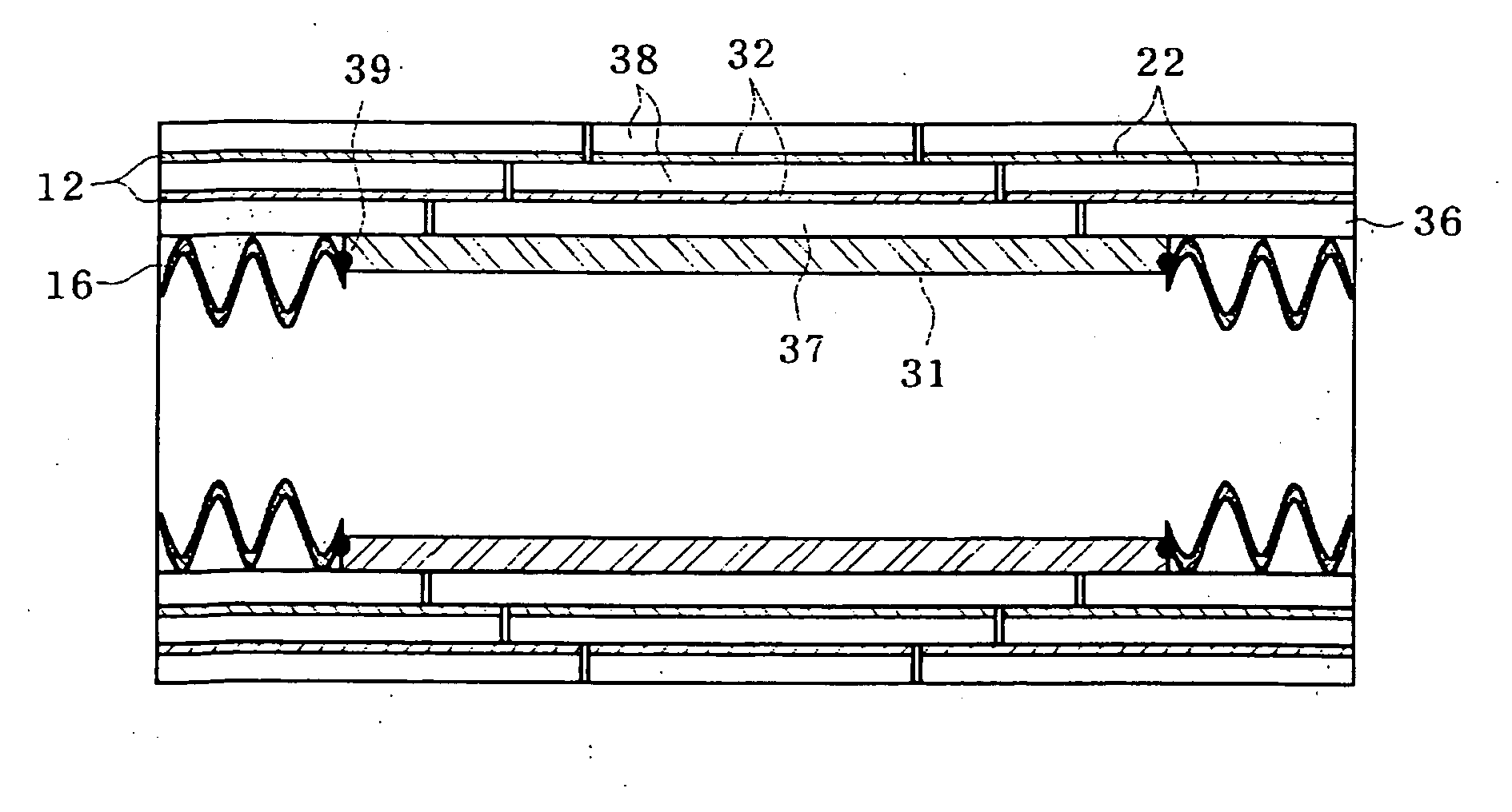
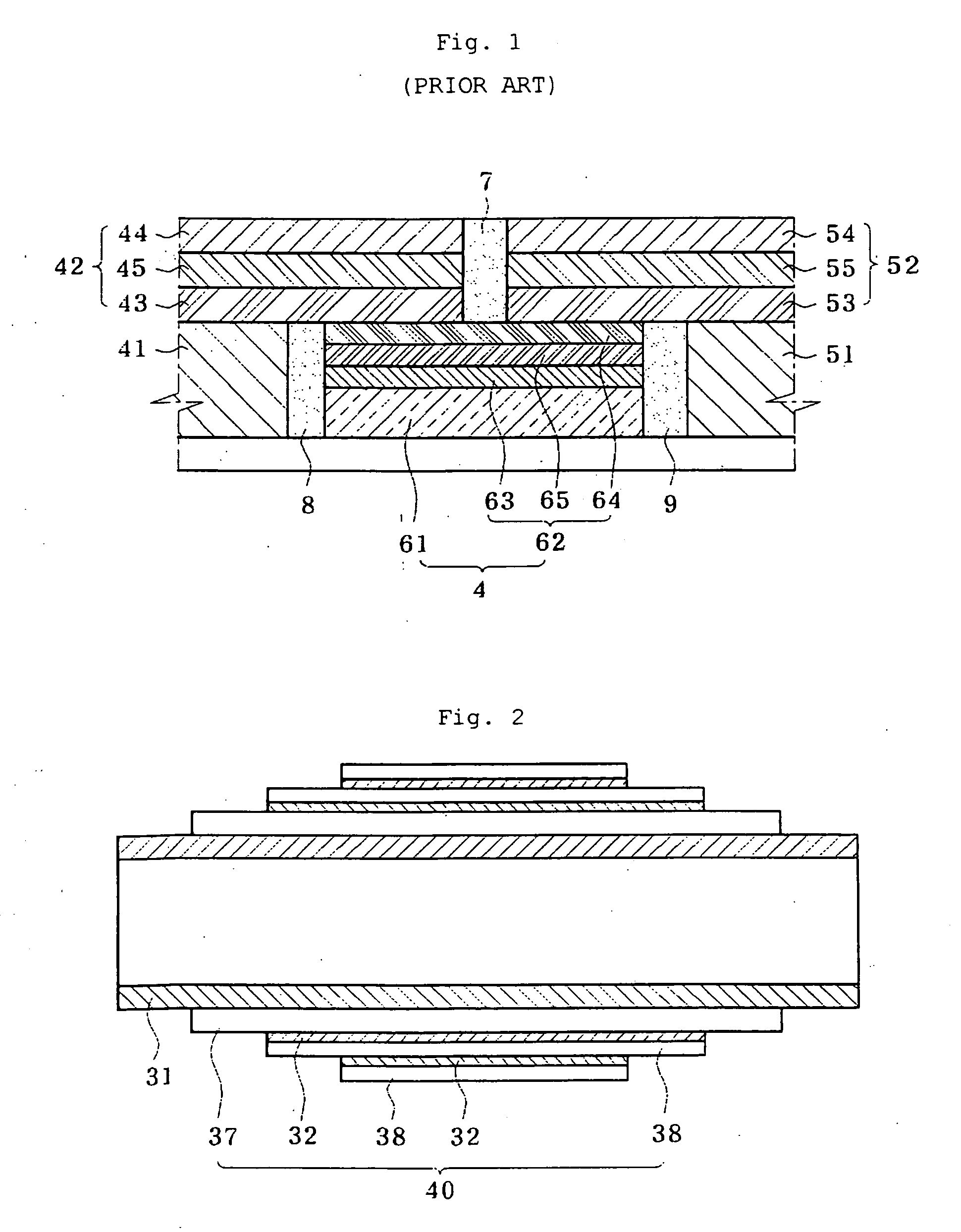
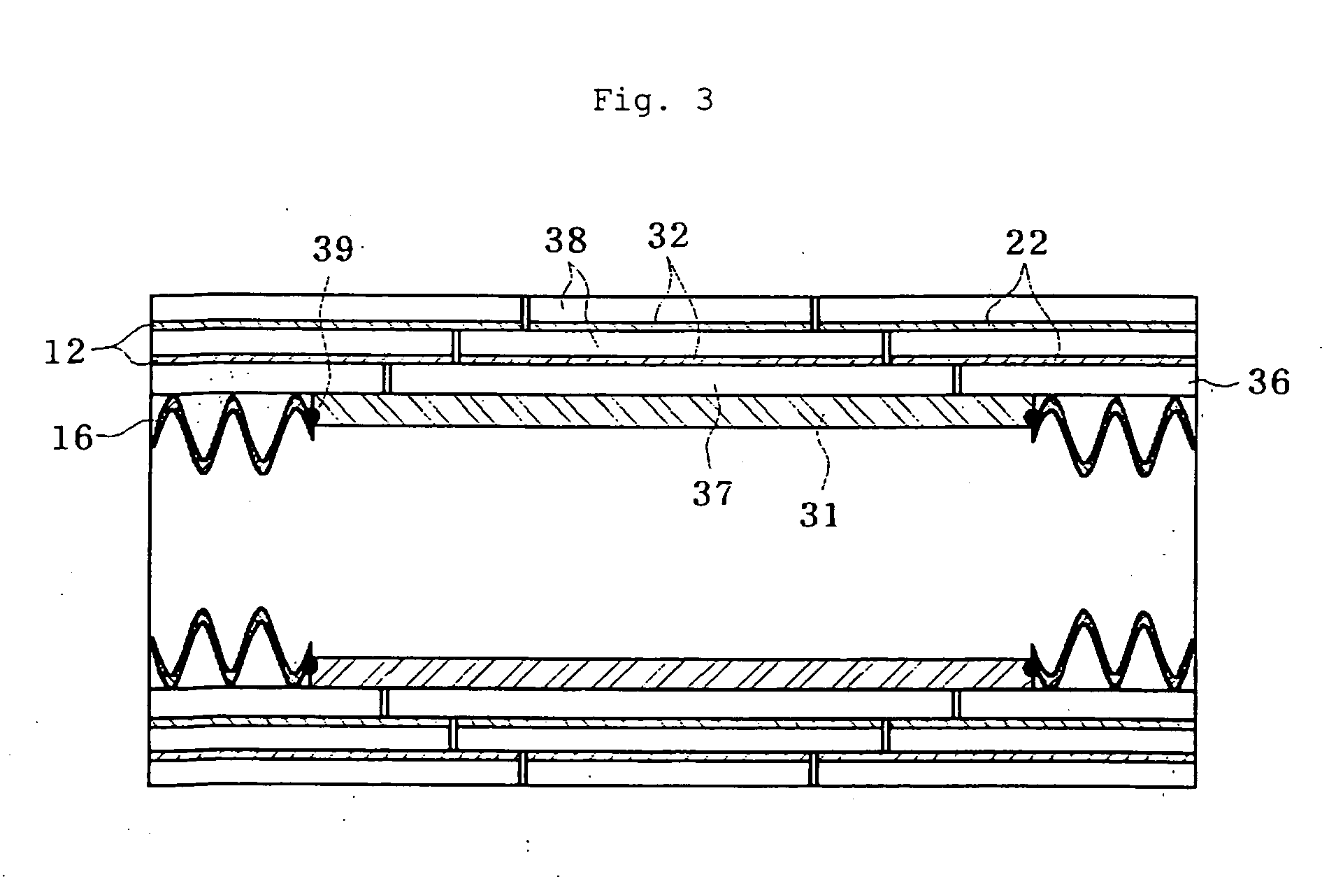
[0021]FIGS. 2 and 3 are cross-sectional views shows a jointing member for a superconducting cable and an intermediate cable-jointing structure using the jointing member according to the present invention, respectively.

[0022] As shown in the drawings, the intermediate cable-jointing structure includes a metal pipe 31 and a jointing sleeve 40. The metal pipe 31 is welded and affixed to formers 16 of both superconducting cables. A plurality of superconductor wires 32 are arranged around a conductive metal tube 37 in a longitudinal direction, and are taped with an Ag tape 38. Next, the superconductor wires 32 are affixed around the metal pipe 31 by means of shrinkage fitting, so that the jointing sleeve 40 is completed.

[0023] The metal pipe 31 is made of a material identical to the formers 16 of the superconducting cables. Both ends of the metal pipe 31 are affixed to the formers 16 of the superconducting cables by welding 39, so that the metal pipe 31 has a high adhesive strength to ...


PUM

PropertyMeasurementUnit
pressureaaaaaaaaaa
temperaturesaaaaaaaaaa

Abstract

An intermediate jointing structure having excellent mechanical and electrical characteristics and method of preparing the same. The intermediate jointing structure includes a metal pipe and a jointing sleeve. The metal pipe is inserted between a pair of superconducting cables and is fixed to the formers by welding. A plurality of superconductor wires, shorter than the conductive metal tube, are arranged around a conductive metal tube in a longitudinal direction. The arranged superconductor wires are taped with Ag tape so as to form the jointing sleeve. The jointing sleeve is jointed and fixed on an outer surface of the metal pipe.

Description

BACKGROUND OF THE INVENTION [0001] 1. Field of the Invention [0002] The present invention relates to a jointing structure for superconducting cable and a method for jointing the superconducting cable, and more particularly to an intermediate joint structure of a superconducting cable that prevents cracks by remarkably improving: physical bonding strength of a jointing interface, a rise in temperature of the refrigerant, and overloading of a cooling system due to such a temperature rise, as well as having excellent electrical characteristics, and a jointing method thereof. [0003] 2. Description of the Related Art [0004] Generally, a power cable using a superconductor transmits a great amount of electric power and has very small power loss in comparison with a conventional power cable. [0005] For the purpose of transmitting a large amount of electric power over a long distance by using the superconducting cable, an intermediate jointing member between superconducting cables is absolut...

Claims


Application Information

Patent Timeline
Patent Type & Authority Applications(United States)
IPC IPC(8): H01B12/00H01R4/68H02G15/34
CPCH01R4/68Y02E40/648H02G15/34Y02E40/60H01B12/00
Inventor JANG, HYUN-MAN
Owner LG CABLE LTD (KR)
Why Eureka
Try Eureka