

Polarizing plate, liquid crystal display using the same and method for manufacturing polarizing plate
- Summary
- Abstract
- Description
- Claims
- Application Information
AI Technical Summary
Benefits of technology
Problems solved by technology
Method used
Image

Examples
first embodiment
(First Embodiment)
In the present invention, in a first embodiment of the curing process, the concave portion is formed by: coating the curing resin composition on the base material or on the concave portion forming substrate; curing the above mentioned curing resin composition by heating or irradiation with ultraviolet ray; disposing the base material and the concave portion forming substrate by laminating them with sandwiching the curing resin obtained by curing; and peeling the concave portion forming substrate from the above mentioned curing resin composition. In this embodiment, for example as shown in FIG. 5, the curing resin composition 12 is coated on the base material 1. Then, the above mentioned curing resin composition 12 is cured by irradiating with ultraviolet ray 21. In FIG. 5, the curing resin composition is coated on the base material 1. However, it may be coated also on the concave portion forming substrate.
In this case, regarding the direction of irradiation with...
second embodiment
(Second Embodiment)
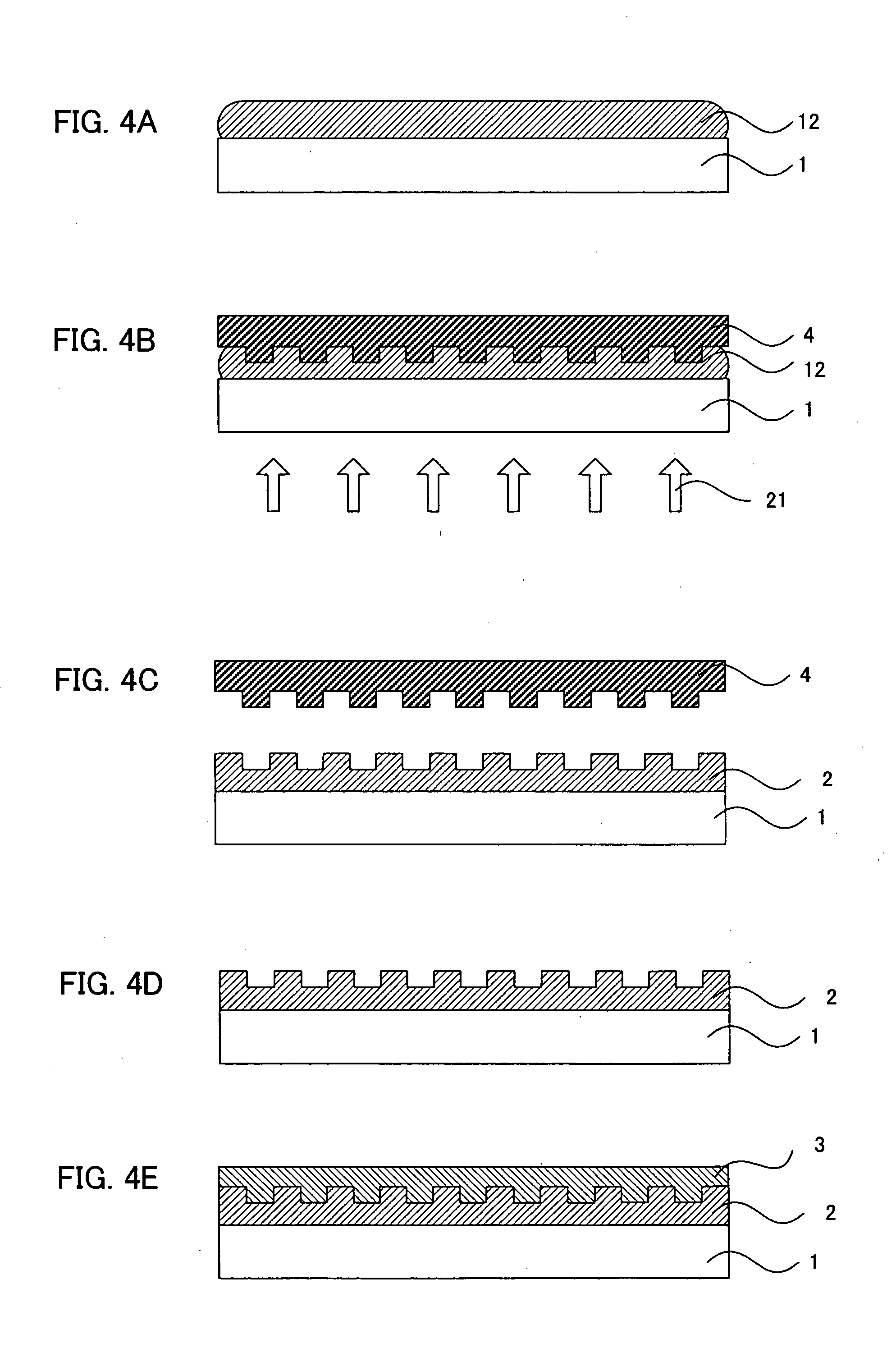
In the present invention, in a second embodiment of the curing process, the concave portion is formed by: coating the curing resin composition on the base material or the concave portion forming substrate; disposing the base material and the concave portion forming substrate by laminating them with sandwiching the above mentioned curing resin composition; curing the above mentioned curing resin composition by heating or irradiation with ultraviolet ray; and peeling off the concave portion forming substrate from the curing resin obtained by curing. In this embodiment, for example as shown in FIG. 4B, the base material 1 and the concave portion forming substrate 4 are disposed by laminating them with sandwiching a curing resin composition 12. Then, the curing resin composition 12 is cured by irradiation with ultraviolet ray 21.
In this case, regarding the direction of irradiation with ultraviolet ray for curing the above mentioned curing resin composition, irradia...
third embodiment
(Third Embodiment)
In the present invention, in a third embodiment of the curing process, the concave portion is formed by: coating the curing resin composition on the base material or the concave portion forming substrate; disposing the base material and concave portion forming substrate by laminating them with sandwiching the above mentioned curing resin composition; peeling the concave portion forming substrate from the above mentioned curing resin composition; and curing the above mentioned curing resin composition by heating or irradiating with ultraviolet ray. In this embodiment, for example as shown in FIG. 6, the concave portion forming substrate 4 is peeled off from the curing resin composition 12. Then, the curing resin composition 12 is cured by irradiation with ultraviolet ray 21.
In this case, regarding the direction of irradiation with energy ray for curing the above mentioned curing resin composition, irradiation may be carried out from the side of the curing resin c...
PUM
 Abstract
Description
Claims
Application Information