Fluid bearing module

a technology of bearing module and fluid bearing, which is applied in the direction of liquid fuel engine, coupling, machine/engine, etc., can solve the problems of high noise, high cost of most commonly used ball bearing, and high cost of miniaturization

Inactive Publication Date: 2005-03-31
IND TECH RES INST
View PDF5 Cites 9 Cited by
  • Summary
  • Abstract
  • Description
  • Claims
  • Application Information

AI Technical Summary

Benefits of technology

[0010] Another objective of the invention is to provide a fluid bearing

Problems solved by technology

The most commonly used ball bearings thus have higher cost than before.
Therefore, the cost for miniaturization is too high.
Moreover, if the ball bearing has any defect, there will be such problems as high noises and insufficient precision during the operation of the rotating device.
In particular, when the ball bearings are used in the optic

Method used


Image

  • Fluid bearing module
  • Fluid bearing module
  • Fluid bearing module

Examples


Embodiment Construction

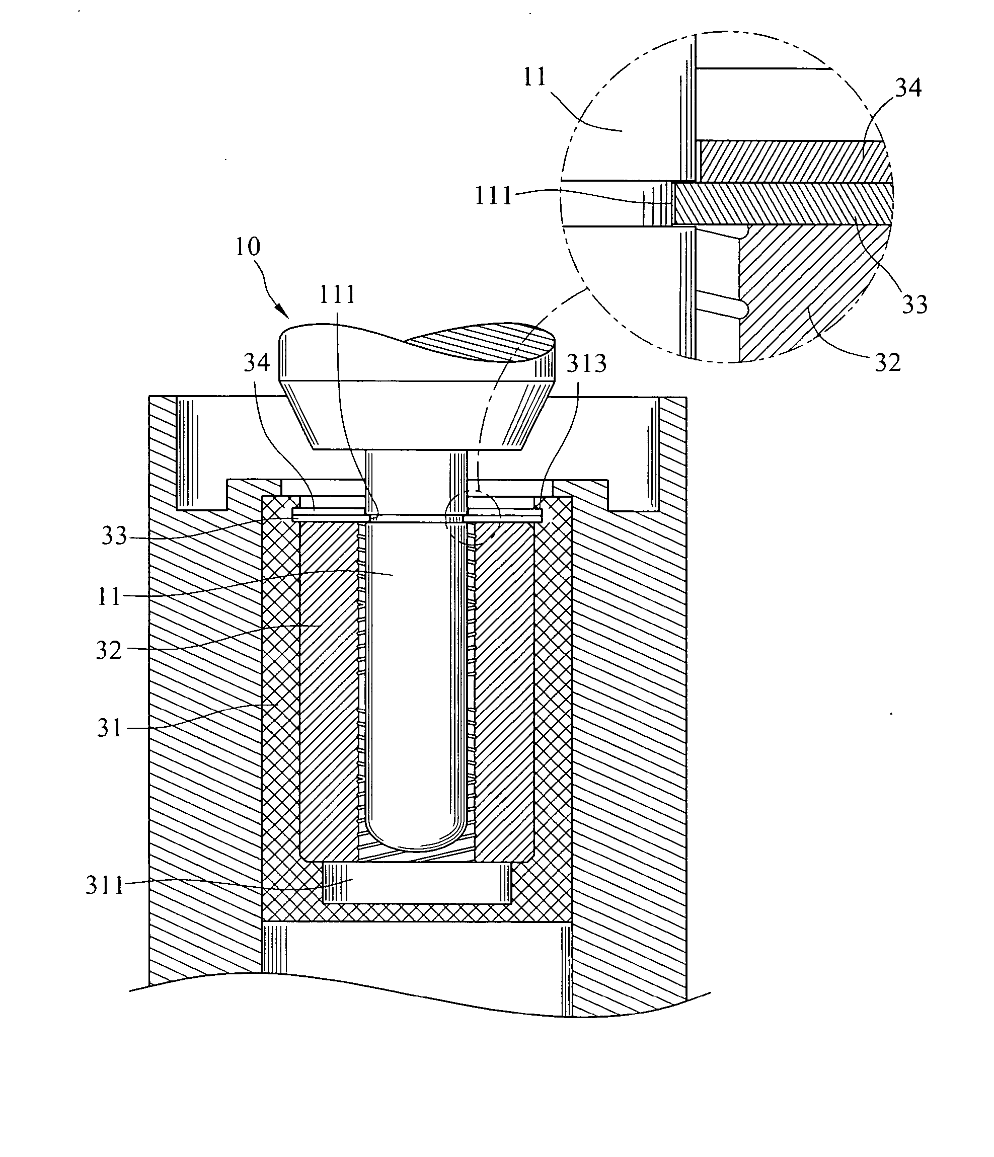
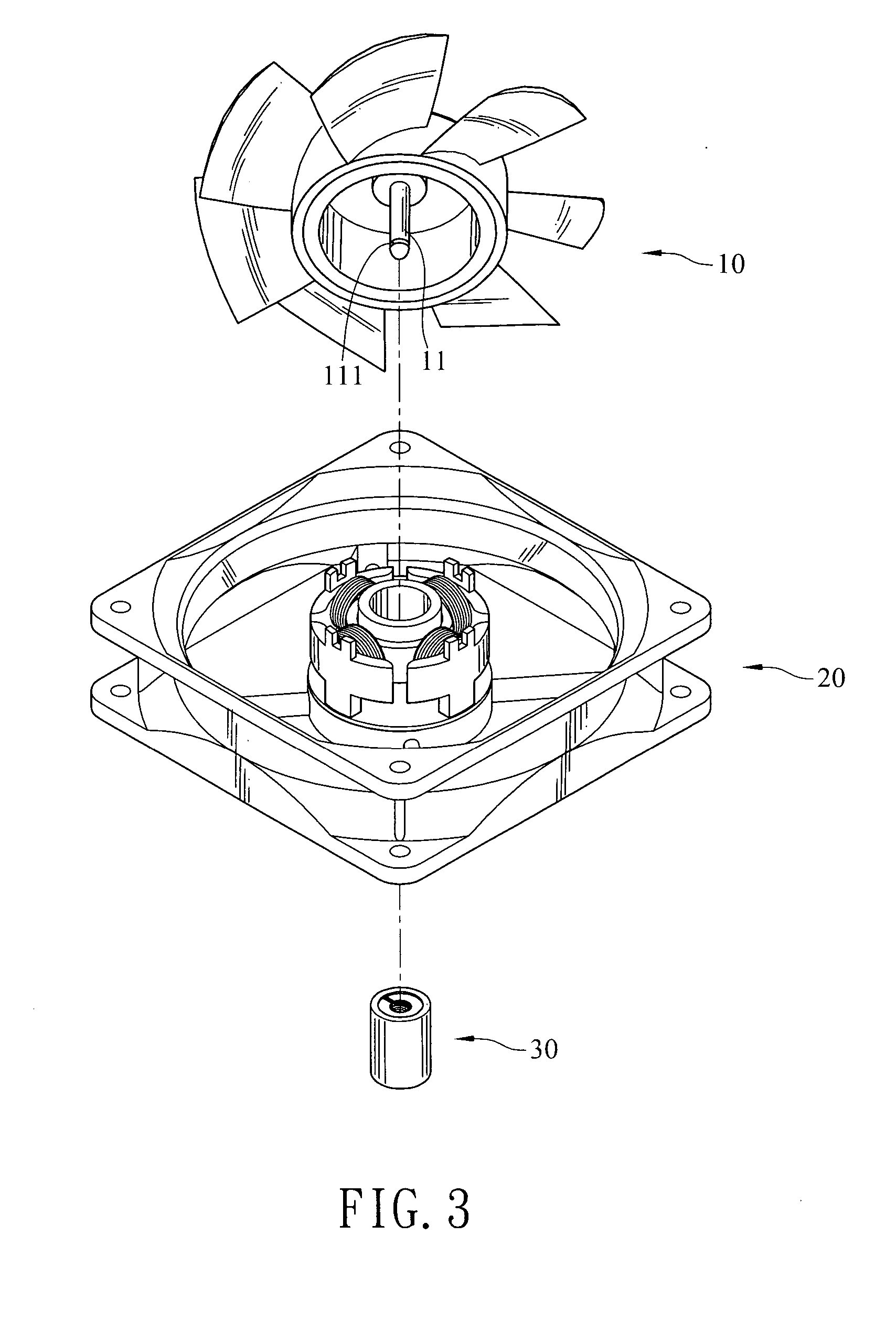
[0024] The invention discloses a fluid bearing module 30 used in motors that output rotational energy. The fan shown in FIG. 3 includes a rotor 10, a stator 20, and a fluid bearing module 30. The rotor 10 is fixed onto the stator 20 by the fluid bearing module 30. The rotor 10 includes several blades installed on its rim. Its inner ring is provided with a permanent magnet. It is installed on the fluid bearing module 30 via an axes 11 and fixed at the center of the stator 20. The stator 20 has a coil winded on several magnetic poles formed on several silicon steel blades. When an electrical current flows through the coil, the magnetic poles produce magnetic forces to repel from the magnetic poles on the stator 20. Therefore, the rotor 10 starts to rotate and outputs rotational energy. Since this portion belongs to the prior art, we do not describe in further detail here.

[0025] The fluid bearing module 30 shown in FIGS. 3 and 4 includes a bearing seat 31, a bearing 32, a deflecting m...


PUM


Abstract

A fluid bearing module has a bearing seat, a bearing, a deflecting member, and an impediment. The bearing seat has a capacity with an opening. The bearing in the capacity has a hollow space for the axis of a rotor to go through, and a lubricant medium is filled in between. The deflecting member protruding from the side near the opening of the bearing seat bends toward the capacity and clips on the rotor axis. The impediment protrudes from the side near the opening of the bearing seat for preventing the deflecting member from bending toward the opening and departing from the rotor. Moreover, the deflecting member and the impediment form a maze to keep the lubricant medium within.

Description

BACKGROUND OF THE INVENTION [0001] 1. Field of Invention [0002] The invention relates to a fluid bearing module for rotating devices and, in particular, to a fluid bearing module that has the functions of preventing the lubricant medium from leaking and the deflecting member from getting loose. [0003] 2. Related Art [0004] The bearings are used in rotating devices to provide support, to reduce friction, and to withstand loads. As modern devices are getting smaller and become compact, the precision requirement on the bearing is also getting higher. The most commonly used ball bearings thus have higher cost than before. For example, for the ball bearings used in motors, the cost is above one third of the total cost of the motor. Therefore, the cost for miniaturization is too high. Moreover, if the ball bearing has any defect, there will be such problems as high noises and insufficient precision during the operation of the rotating device. In particular, when the ball bearings are used...

Claims


Application Information

Patent Timeline
IPC IPC(8): F04D29/04F04D29/057F04D29/06F04D29/12F16C33/10
CPCF04D29/057F04D29/063F04D29/122Y10T403/54F16C33/107Y10S384/903F16C33/103
Inventor SHIH, WUN-CHANGHUANG, CHING-HSINGCHANG, YU-HSIU
Owner IND TECH RES INST
Why Eureka
Try Eureka