Device for the dosing of a reducing agent

a technology of reducing agent and device, which is applied in the direction of lighting and heating apparatus, combustion types, separation processes, etc., can solve the problems of large metering system and complicated production

Inactive Publication Date: 2005-03-31
ROBERT BOSCH GMBH
View PDF11 Cites 40 Cited by
  • Summary
  • Abstract
  • Description
  • Claims
  • Application Information

AI Technical Summary

Problems solved by technology

The metering system described is relatively large and complicated to produce,

Method used


Image

  • Device for the dosing of a reducing agent
  • Device for the dosing of a reducing agent
  • Device for the dosing of a reducing agent

Examples


Embodiment Construction

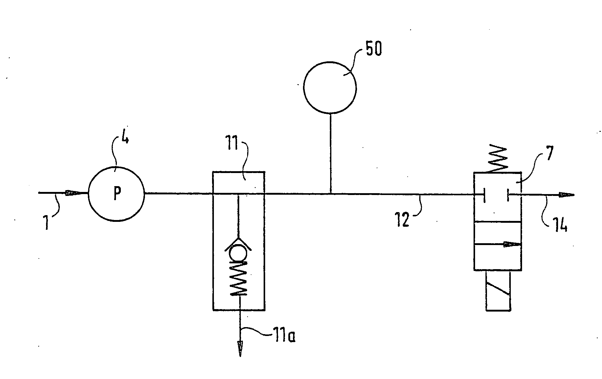
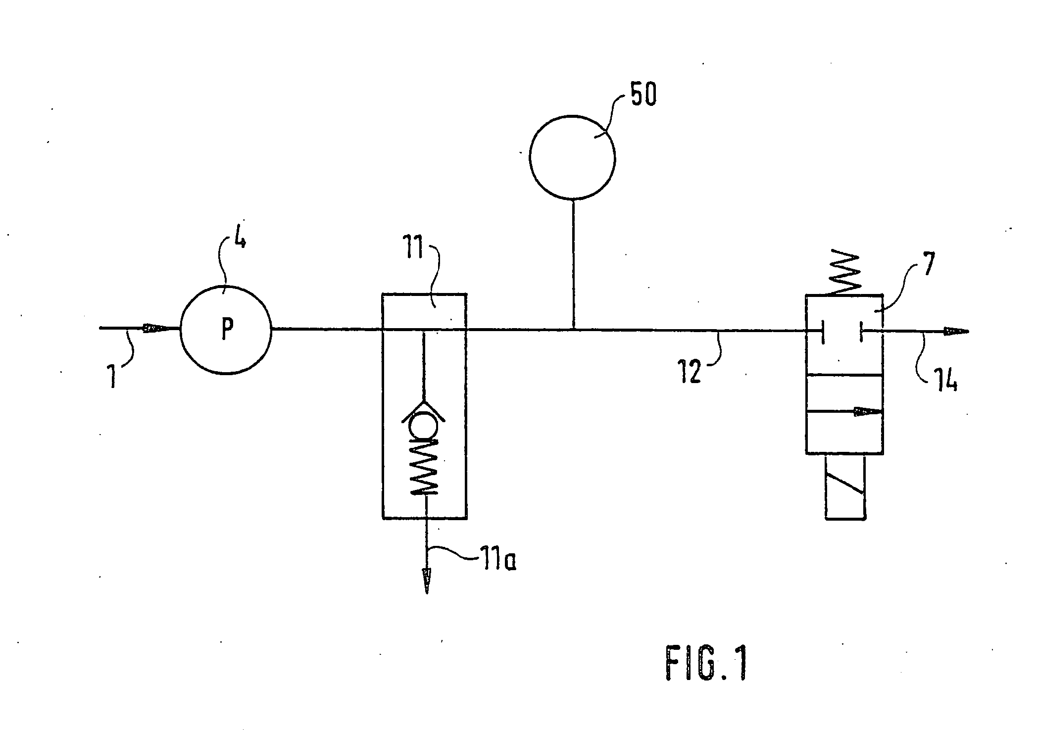
[0015] In FIG. 1, reference numeral 1 indicates the inlet to the metering apparatus, by way of which a urea-water solution is supplied to the apparatus. A metering pump 4 aspirates the fluid. The pump 4 is rpm-controlled via a stepping motor 4a. A pressure regulator 11 carries any excess pumped quantity of fluid via the outlet 11a of the pressure regulator either back to the inlet of the metering apparatus or to the metering pump or to a urea tank, not shown in detail, from which the metering pump 4 is supplied via the inlet 1. The line 12 connecting the inlet 1, pump 4 and pressure regulator 11 carries the pumped fluid onward to a metering valve 7. A pressure sensor 50 for measuring the pressure in the line 12 is mounted upstream of the metering valve. The metering valve is electrically triggerable and dispenses the fluid in accordance with the electrical triggering to components connected to the outlet 14. This is for example a mixing chamber, not shown in detail but already descr...


PUM

PropertyMeasurementUnit
Pressureaaaaaaaaaa
Pressureaaaaaaaaaa
Elasticityaaaaaaaaaa

Abstract

An apparatus for metering a urea or a urea-water solution for delivery to a catalytic converter assembly for removing nitrogen oxides from the exhaust gases of a Diesel engine, includes a housing block supporting function components communicating via a line, formed by recesses in the housing block, for transporting the reducing agent, and the walls of the line are formed by the housing block. This apparatus assures a simple line layout for reducing agent with a minimum number of sealing points that is accordingly appropriate for large-scale mass production.

Description

PRIOR ART [0001] The invention is based on an apparatus for metering a reducing agent, in particular a urea or a urea-water solution, in the context of catalytic posttreatment of exhaust gases, as generically defined by the preamble to the main claim. [0002] To achieve a reduction in NOx components in exhaust gases, reduction catalytic converters have been developed, especially for Diesel engines, and are typically classified as either so-called SCR catalytic converters (for Selective Catalytic Reduction) or reservoir-type catalytic converters. The so-called SCR catalytic converters are regenerated by delivering a reducing agent comprising urea and / or ammonia, while the so-called reservoir-type catalytic converters are regenerated in so-called rich exhaust gas phases with hydrocarbons from the entrained internal combustion engine fuel. [0003] It is known for the various components of a metering system to be made to communicate via hoses. From German Patent Application 199 46 900.8, ...

Claims


Application Information

Patent Timeline
IPC IPC(8): F01N3/08B01D53/94F01N3/20
CPCF01N3/2066F01N3/36F01N2610/02Y02T10/24F01N2610/14F01N2610/1433F01N2610/1446F01N2610/10Y02T10/12F01N3/20
Inventor HUBER, SVENMAYER, HANSPETERMUELLER, GERHARDOFFENHUBER, MICHAELMOELL, ALEXANDERMOELL, HELMUTMOELL, BRIGITTE
Owner ROBERT BOSCH GMBH
Why Eureka
Try Eureka