Vehicle control apparatus

a technology for controlling apparatuses and vehicles, applied in the direction of pedestrian/occupant safety arrangements, instruments, tractors, etc., can solve problems such as not controlling vehicles

Inactive Publication Date: 2005-03-31
ADVICS CO LTD
View PDF11 Cites 45 Cited by
  • Summary
  • Abstract
  • Description
  • Claims
  • Application Information

AI Technical Summary

Benefits of technology

[0021] Preferably, the instruction-signal generation means is configured to continue the modification of the instruction signal until th

Problems solved by technology

However, the conventional technique does not control the vehicle after occurrence of collision of the vehicle, and gi

Method used


Image

  • Vehicle control apparatus
  • Vehicle control apparatus
  • Vehicle control apparatus

Examples


first embodiment

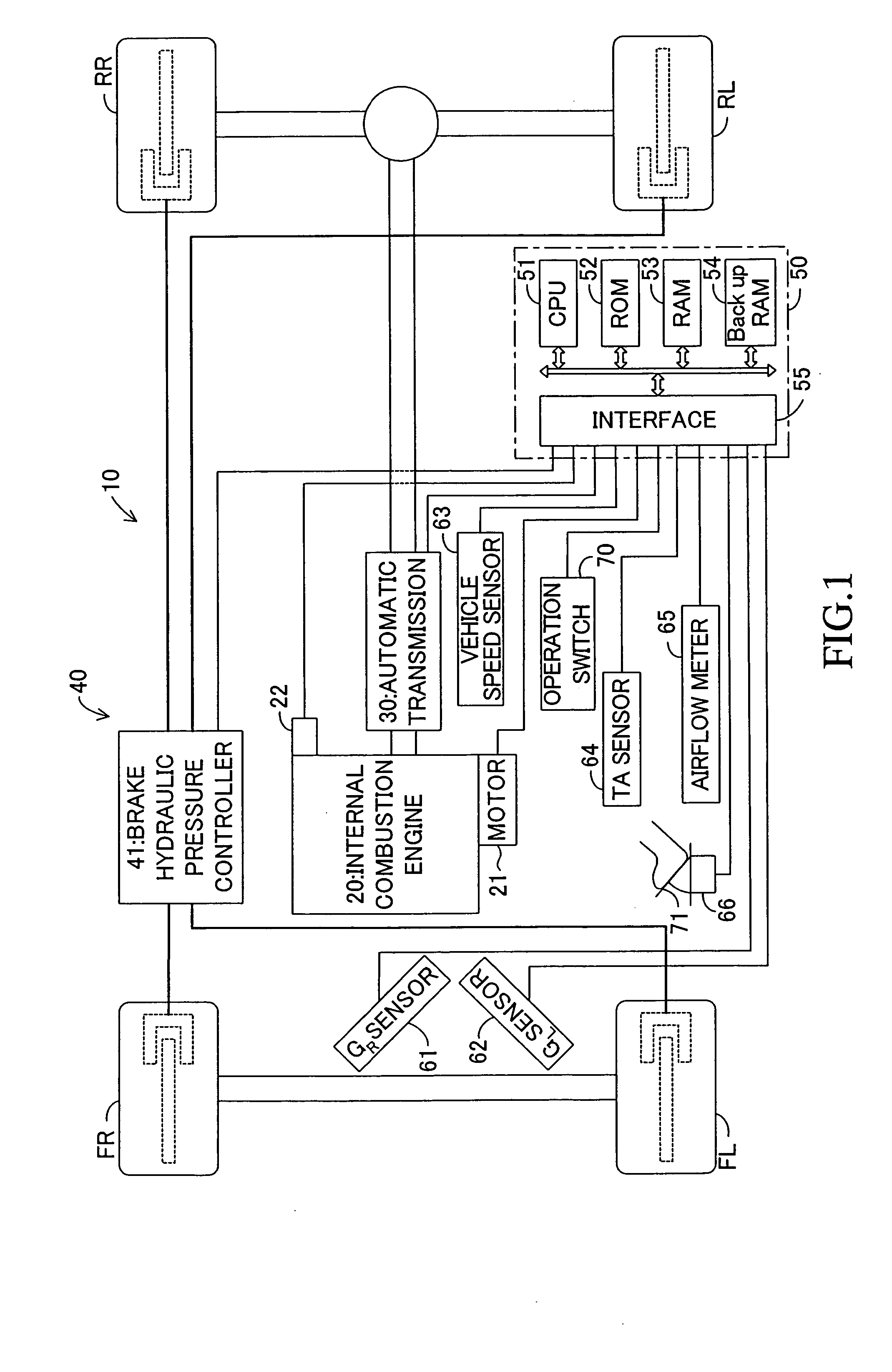
[0028]FIG. 1 schematically shows the structure of a vehicle control apparatus 10 according to a first embodiment of the present invention. The vehicle control apparatus 10 includes an internal combustion engine 20, an automatic transmission 30, a brake apparatus 40, and an electric controller (ECU) 50.

[0029] The internal combustion engine 20 is mounted on the vehicle, and serves as a drive source which generates a drive force for driving the vehicle. The internal combustion engine 20 includes a motor 21 for controlling the opening of a throttle valve in accordance with an instruction signal; and an injector 22 for injecting fuel. The internal combustion engine 20 generates a drive force (output torque), and changes the generated drive force when at least the motor 21 and the injector 22 are controlled.

[0030] The automatic transmission 30 is configured in such a manner that, through control of clutches and brakes of the automatic transmission 30 by means of hydraulic pressure, one ...

second embodiment

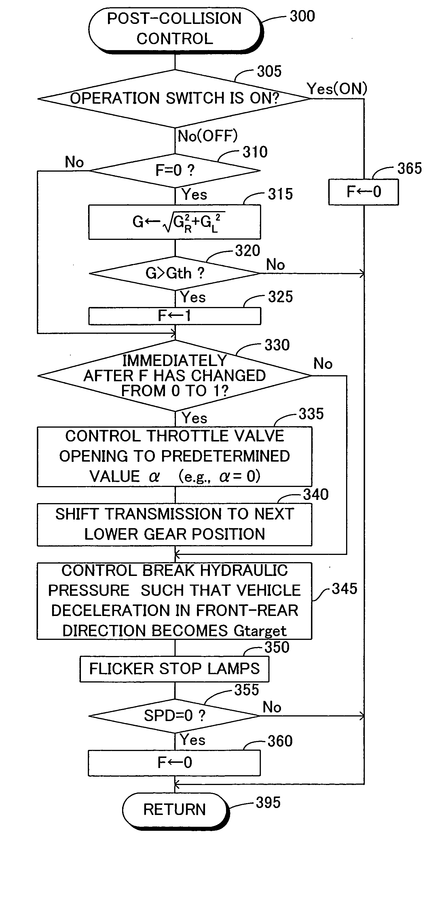
[0078] Next, a vehicle control apparatus according to a second embodiment of the present invention will be described. The vehicle control apparatus according to the second embodiment differs from the vehicle control apparatus 10 of the first embodiment only in that the CPU 51 of the vehicle control apparatus according to the second embodiment executes, at predetermined intervals, the routine (program) shown by a flowchart of FIG. 4 in place of that shown by the flowchart of FIG. 3. Therefore, this difference will be mainly described. Notably, in FIG. 4, those steps which are identical with those of FIG. 3 are denoted by the same step numbers. Further, the operation switch used in the second embodiment is a switch for designating whether to automatically control a drive force corresponding to a drive operation performed by the driver so that the drive force does not exceed a predetermined level when a collision of the vehicle is determined to have occurred.

[0079] In this embodiment ...


PUM


Abstract

An electric controller starts post-collision control when an acceleration of the vehicle detected by means of sensors mounted on the vehicle is greater than an acceleration threshold (i.e., after occurrence of a collision of a vehicle). In the post-collision control, the electric controller fixes the throttle valve opening to a predetermined value, and shifts the transmission from the present gear position to an adjacent lower-side gear position. Moreover, the electric controller controls the hydraulic pressure of the brake such that the vehicle deceleration in the front-rear direction detected by means of the sensors becomes a target deceleration.

Description

BACKGROUND OF THE INVENTION [0001] 1. Field of the Invention [0002] The present invention relates to a vehicle control apparatus for controlling a vehicle after occurrence of a collision. [0003] 2. Description of the Related Art [0004] Conventionally, there have been proposed various vehicle control techniques for preventing accidental collisions of vehicles. For example, Japanese Patent Application Laid-Open (kokai) No. 2002-067843 (paragraph 0006 and FIG. 5) proposes a technique for avoiding accidental collision of a vehicle. In this technique, at least one of a collision allowance time, which is a time necessary to avoid a collision with an object, and a collision allowance distance, which is a distance necessary to avoid a collision with the object, is calculated on the basis of the speed and acceleration of the vehicle, the speed and acceleration of the object, and the maximum deceleration calculated from the surface μ gradient of a road surface along which the vehicle is trave...

Claims


Application Information

Patent Timeline
IPC IPC(8): B60K28/10B60R21/00B60K28/14B60R21/01B60T7/12B60T7/22B60T8/00B60W10/00B60W10/04B60W10/06B60W10/10B60W10/11B60W10/18B60W10/188F02D29/02F16H59/50F16H61/02F16H61/68G06F7/70
CPCB60K28/14B60T7/22B60T2201/024B60W2720/106B60W10/184B60W30/18009B60W10/10
Inventor NAGATA, YUJI
Owner ADVICS CO LTD
Why Eureka
Try Eureka