Multi-step release method for electrochemically fabricated structures

a technology of electrochemical fabrication and release method, which is applied in the direction of liquid/solution decomposition chemical coating, instruments, waveguides, etc., can solve the problems of destructive separation of masking material and substrate, and achieve the effect of improving the reliability of electrochemical fabrication

Inactive Publication Date: 2005-04-07
MICROFAB
View PDF4 Cites 41 Cited by
  • Summary
  • Abstract
  • Description
  • Claims
  • Application Information

AI Technical Summary

Benefits of technology

[0034] An object of some embodiments of various aspects of the invent

Problems solved by technology

The CC mask plating process is distinct from a “through-mask” plating process in that in a through-mas

Method used


Image

  • Multi-step release method for electrochemically fabricated structures
  • Multi-step release method for electrochemically fabricated structures
  • Multi-step release method for electrochemically fabricated structures

Examples


Embodiment Construction

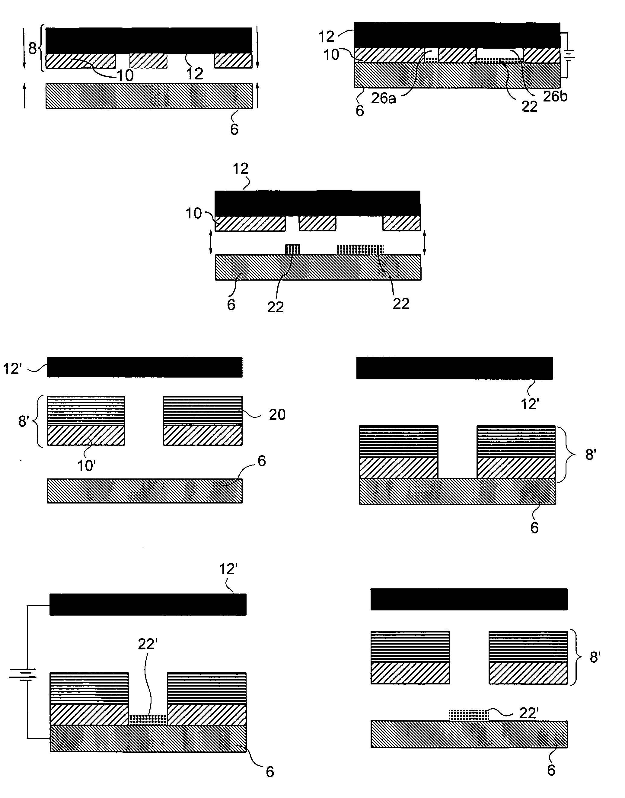
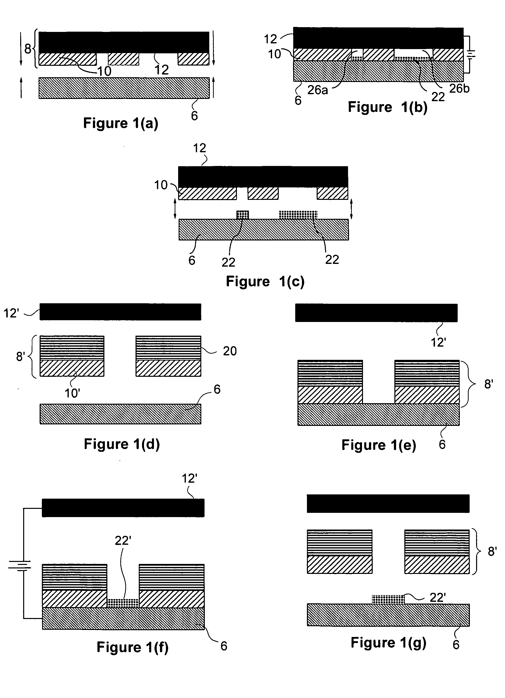
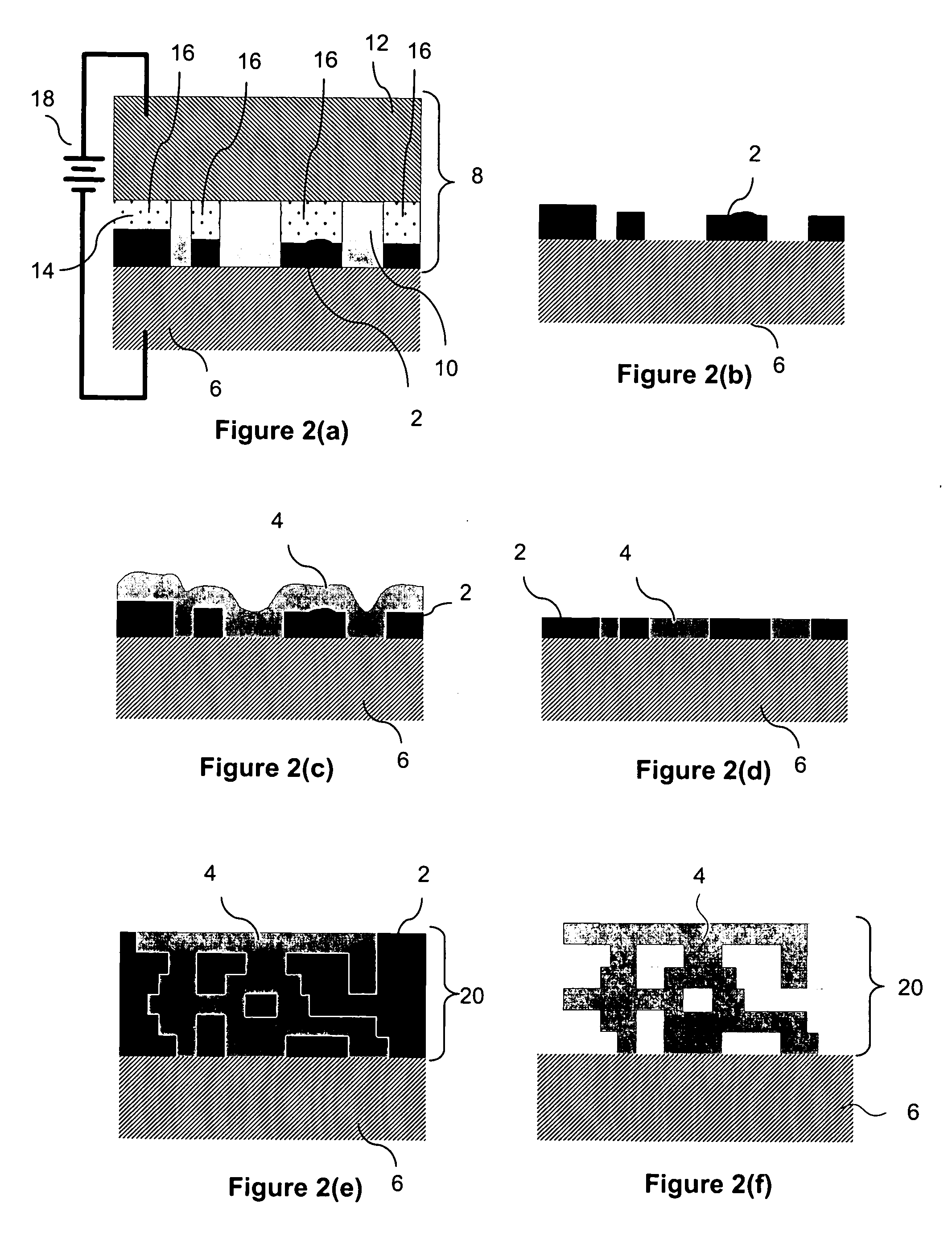
[0063] FIGS. 1(a)-1(g), 2(a)-2(f), and 3(a)-3(c) illustrate various features of one form of electrochemical fabrication that are known. Other electrochemical fabrication techniques are set forth in the '630 patent referenced above, in the various previously incorporated publications, in various other patents and patent applications incorporated herein by reference, still others may be derived from combinations of various approaches described in these publications, patents, and applications, or are otherwise known or ascertainable by those of skill in the art from the teachings set forth herein. All of these techniques may be combined with those of the various embodiments of various aspects of the invention explicitly set forth herein to yield enhanced embodiments. Still other embodiments may be derived from combinations of the various embodiments explicitly set forth herein.

[0064] FIGS. 4(a)- 4(i) illustrate various stages in the formation of a single layer of a multi-layer fabrica...


PUM

PropertyMeasurementUnit
Forceaaaaaaaaaa
Structureaaaaaaaaaa

Abstract

Multi-layer structures are electrochemically fabricated from at least one structural material (e.g. nickel), that is configured to define a desired structure and which may be attached to a substrate, and from at least one sacrificial material (e.g. copper) that surrounds the desired structure. After structure formation, the sacrificial material is removed by a multi-stage etching operation. In some embodiments sacrificial material to be removed may be located within passages or the like on a substrate or within an add-on component. The multi-stage etching operations may be separated by intermediate post processing activities, they may be separated by cleaning operations, or barrier material removal operations, or the like. Barriers may be fixed in position by contact with structural material or with a substrate or they may be solely fixed in position by sacrificial material and are thus free to be removed after all retaining sacrificial material is etched.

Description

RELATED APPLICATIONS [0001] This application is a Continuation-in-Part of both U.S. patent application No. 10 / 434,497 filed May 7, 2003 and U.S. patent application No. 10 / 607,931 filed Jun. 27, 2003; U.S. patent application No. 10 / 434,497 claims benefit of U.S. Provisional Patent Application No. 60 / 379,184, filed May 7, 2002, and No. 60 / 392,531, filed Jun. 27, 2002. U.S. patent application Ser. No. 10 / 607,931 claims benefit of U.S. Provisional Patent Application No. 60 / 392,531, filed Jun. 27, 2002, No. 60 / 415,374, filed Oct. 1, 2002, No. 60 / 464,504, filed Apr. 21, 2003, and 60 / 476,554, filed on Jun. 6, 2003; U.S. patent application Ser. No. 10 / 607,931 is also a continuation-part of U.S. patent application Ser. No. 10 / 309,521, filed on Dec. 3, 2002 and Ser. Nos. 10 / 434,497, 10 / 434,103, 10 / 434,295, and 10 / 434,519 each filed on May 7, 2003; U.S. patent application Ser. No. 10 / 309,521 claims benefit of U.S. Provisional Patent Application No. 60 / 338,638, filed on Dec. 3, 2001, No. 60 / 340...

Claims


Application Information

Patent Timeline
IPC IPC(8): B81B3/00G01P15/08G01P15/125H01P1/202H01P3/06H01P5/18H01P11/00H05K3/46
CPCB81B2201/042C23C18/1651B81C2201/0109B81C2201/0197G01P15/0802G01P15/125H01P1/202H01P3/06H01P5/183H01P11/00H01P11/005H01P11/007H05K3/4647C25D1/003C23C18/1605B81C1/00126
Inventor COHEN, ADAM L.LOCKARD, MICHAEL S.MCPHERSON, DALE S.
Owner MICROFAB
Why Eureka
Try Eureka