Cathode ray tube

Inactive Publication Date: 2005-04-07
MITSUBISHI ELECTRIC CORP
View PDF5 Cites 2 Cited by
  • Summary
  • Abstract
  • Description
  • Claims
  • Application Information

AI Technical Summary

Benefits of technology

[0009] With such an arrangement, the resistance to external pressure can be improved, and the deflection power consumption can be reduced. Further, the degradation of the image can be prevented. Addi

Problems solved by technology

Recently, the cathode ray tube has a relatively high deflection frequency, and therefore a deflection power consumption (i.e., an electrical power consumed by the deflection yoke) increases.
Thus, a crack may be formed at the corner of the rectangular-shaped portion, with the result that the resistance to external pressure (i.e., atmospheric pressure) decreases.
However, if the narrow par

Method used


Image

  • Cathode ray tube
  • Cathode ray tube
  • Cathode ray tube

Examples


Example

[0020] Embodiment 1.

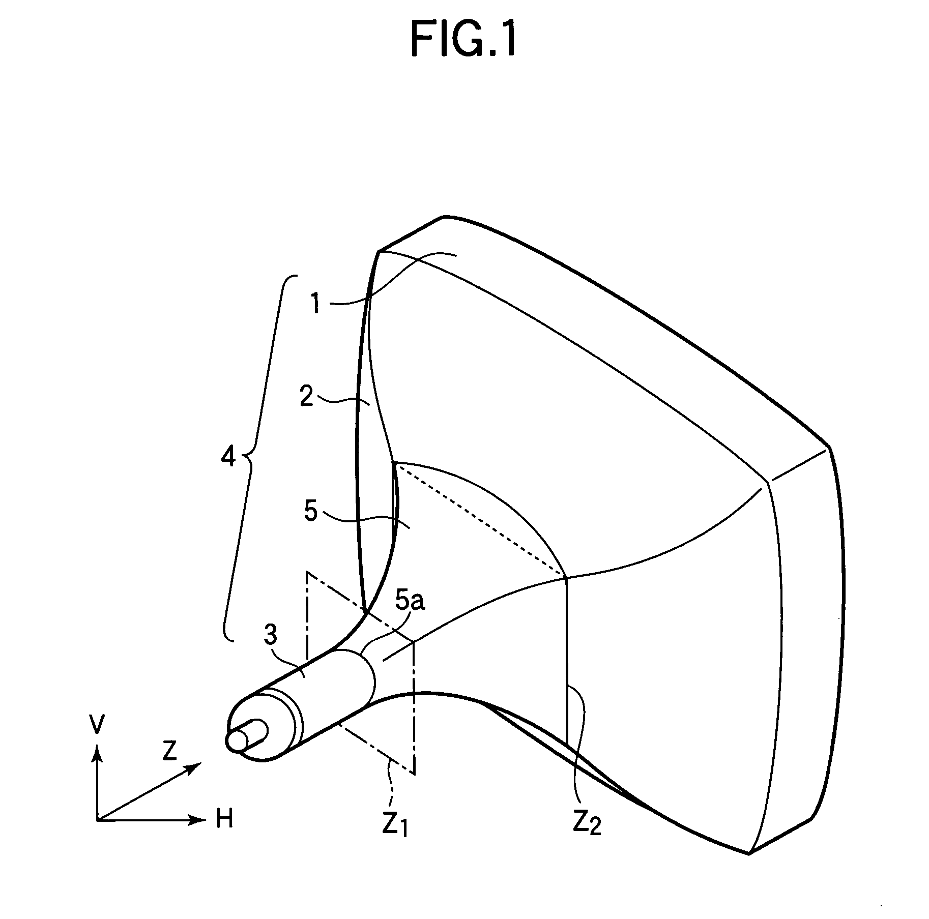
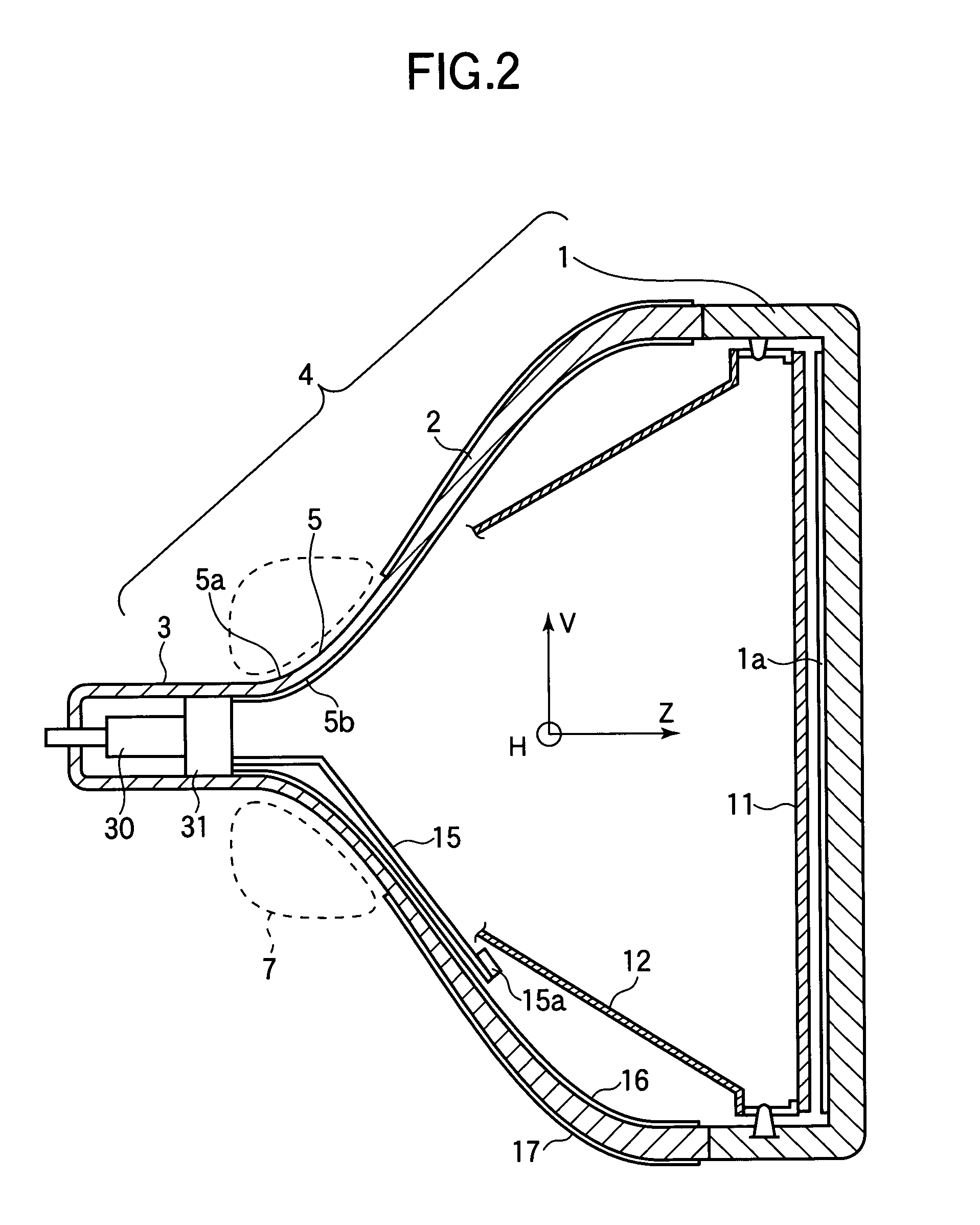
[0021]FIGS. 1 and 2 are a perspective view and a sectional view of a cathode ray tube according to Embodiment 1. As shown in FIG. 1, the cathode ray tube according to Embodiment 1 includes a vacuum enclosure 4. The vacuum enclosure 4 includes a rectangular panel 1, a funnel (i.e., a substantially funnel-shaped portion) 2 connected to the panel 1, and a cylindrical neck 3 connected to a narrow part of the funnel 2. The funnel 2 has a structure in which a so-called tube axis (Z-axis) is defined. As shown in FIG. 2, a screen 1a is formed on the inner surface of the panel 1. The screen 1a has phosphors emitting blue, green and red light. The screen 1a has a rectangular shape. The horizontal (H) axis is defined as an axis in parallel with long sides of the screen 1a. The vertical (V) axis is defined as an axis in parallel with short sides of the screen 1a. The ratio (i.e., an aspect ratio) of the dimension M of the screen 1a along H-axis to the dimension N of the scr...

Example

[0039] Embodiment 2.

[0040]FIG. 6 is a perspective view of a cathode ray tube according to Embodiment 2. FIGS. 7A and 7B are schematic views illustrating the sectional shapes of the yoke-mounting portion 6, cut by the plane perpendicular to Z-axis, at the rear end position Z1 and the front end position Z2.

[0041] The sectional shape of the yoke-mounting portion 6, cut by the plane perpendicular to Z-axis, is the circular shape at the rear end position Z1 as shown in FIG. 7A. The sectional shape of the yoke-mounting portion 6 gradually varies from the circular shape to the substantially barrel shape (FIG. 7B), as the position shifts from the rear end position Z1 to the front end position Z2. In FIG. 7B, the yoke-mounting portion 6 includes two straight side walls 61 and two arc-shaped side walls 62. The straight side walls 61 straightly extend along H-axis. The arc-shaped side walls 62 extend in the form of circular arcs having a radius Rd and having the center of curvature aligned o...


PUM


Abstract

A cathode ray tube has a vacuum enclosure including a panel (1) having a screen (1a), a funnel (2) connected to the panel (1), and a neck (3) connected to the narrow part of the funnel (2). The funnel (2) has a yoke-mounting portion (5) on which a deflection yoke (7) is mounted. The sectional shape of the yoke-mounting portion (5), cut by a plane perpendicular to the tube axis of the funnel (2), varies from a circular shape to a substantially barrel shape having a maximum dimension at least in a direction of the horizontal axis or the vertical axis, as the position shifts from the neck (3) side to the panel (1) side of the yoke-mounting portion (5). With such an arrangement, the resistance to the external pressure can be improved, and the deflection power consumption can be reduced.

Description

BACKGROUND OF THE INVENTION [0001] This invention relates to a cathode ray tube employed in a television, a display device of a computer or the like. [0002] A cathode ray tube employed in a television, a display device of a computer or the like has an electron gun that emits an electron beam and a deflection yoke that deflects the electron beam emitted by the electron gun. The deflection yoke deflects the electron beam in directions of a horizontal axis and a vertical axis on a screen, so that the screen is scanned. The deflection yoke is mounted on the outer surface of a narrow part of a funnel, and the electron gun is mounted in a cylindrical neck connected to the narrow part of the funnel. Recently, the cathode ray tube has a relatively high deflection frequency, and therefore a deflection power consumption (i.e., an electrical power consumed by the deflection yoke) increases. In order to reduce the deflection power consumption, the deflection yoke needs to be located proximately...

Claims


Application Information

Patent Timeline
IPC IPC(8): H01J29/86
CPCH01J2229/8606H01J29/861
Inventor MATSUURA, YOSHIHITOAOKI, KIYOSHIMURATA, MIZUKINAGASAWA, KAZUSHITOKUNAGA, HISANOBU
Owner MITSUBISHI ELECTRIC CORP
Why Eureka
Try Eureka