Low part count blower-motor assembly in common housing

a blower motor and common housing technology, applied in the direction of positive displacement liquid engines, piston pumps, liquid fuel engines, etc., can solve the problems of high part count of these assemblies, high noise generation, and relatively inefficient assembly and manufacturing procedures

Inactive Publication Date: 2005-04-07
THE BERGQUIST TORRINGTON
View PDF6 Cites 8 Cited by
  • Summary
  • Abstract
  • Description
  • Claims
  • Application Information

AI Technical Summary

Benefits of technology

[0004] It is a general object of the present invention to provide a low part count blower-motor assembly in a common housing whereby to eliminate air leakage between the motor and blower wheel thus improving performance, reducing noise generation, enhancing motor cooling, and protecting the motor from harmful environmental conditions. A further object of the invention is to provide for improved cooling of the motor by diverting a portion of the main air stream passing through the blower and directing it through the motor stator.
[0005] Another object of the invention is to provide integrated unitary stator and rotor assemblies, and in some instances integrated unitary rotor and blower or impeller assemblies thus aiding in minimizing part counts.
[0009] Preferably the construction of the stator assembly is in accordance with the teaching of U.S. application Ser. No. 10 / 679,143, Improved Permanent Magnet Motor, filed Oct. 2, 2003, herein incorporated herein by reference, with the entire assembly overmolded in an injection molding process resulting in a unitary component. Similarly, the rotor assembly is preferably constructed in accordance with the teaching of U.S. Application 60 / 508,413, Method for Making Rotor for Permanent Magnet Electric Machine, filed Oct. 2, 2003, herein by reference, with the entire assembly overmolded in am injection molding process resulting in a unitary component. A bearing tower, to be described herein below, is also constructed in accordance with the teaching of U.S. Application 60 / 442,407, herein by reference, with the entire assembly overmolded in an injection molding process resulting in a unitary component. Additionally, it should be noted that the rotor may be molded integrally with the impeller, thus further reducing the number of parts.

Problems solved by technology

Part counts in these assemblies is high due primarily to the complexity of the electric motors and this of course leads to relatively inefficient assembly and manufacturing procedures.
This arrangement results in high noise generation, air leakage at the shaft opening in the blower housing, air leakage through the motor bearings, and motor cooling problems if the blower is contained within an enclosed space.

Method used


Image

  • Low part count blower-motor assembly in common housing
  • Low part count blower-motor assembly in common housing
  • Low part count blower-motor assembly in common housing

Examples


Embodiment Construction

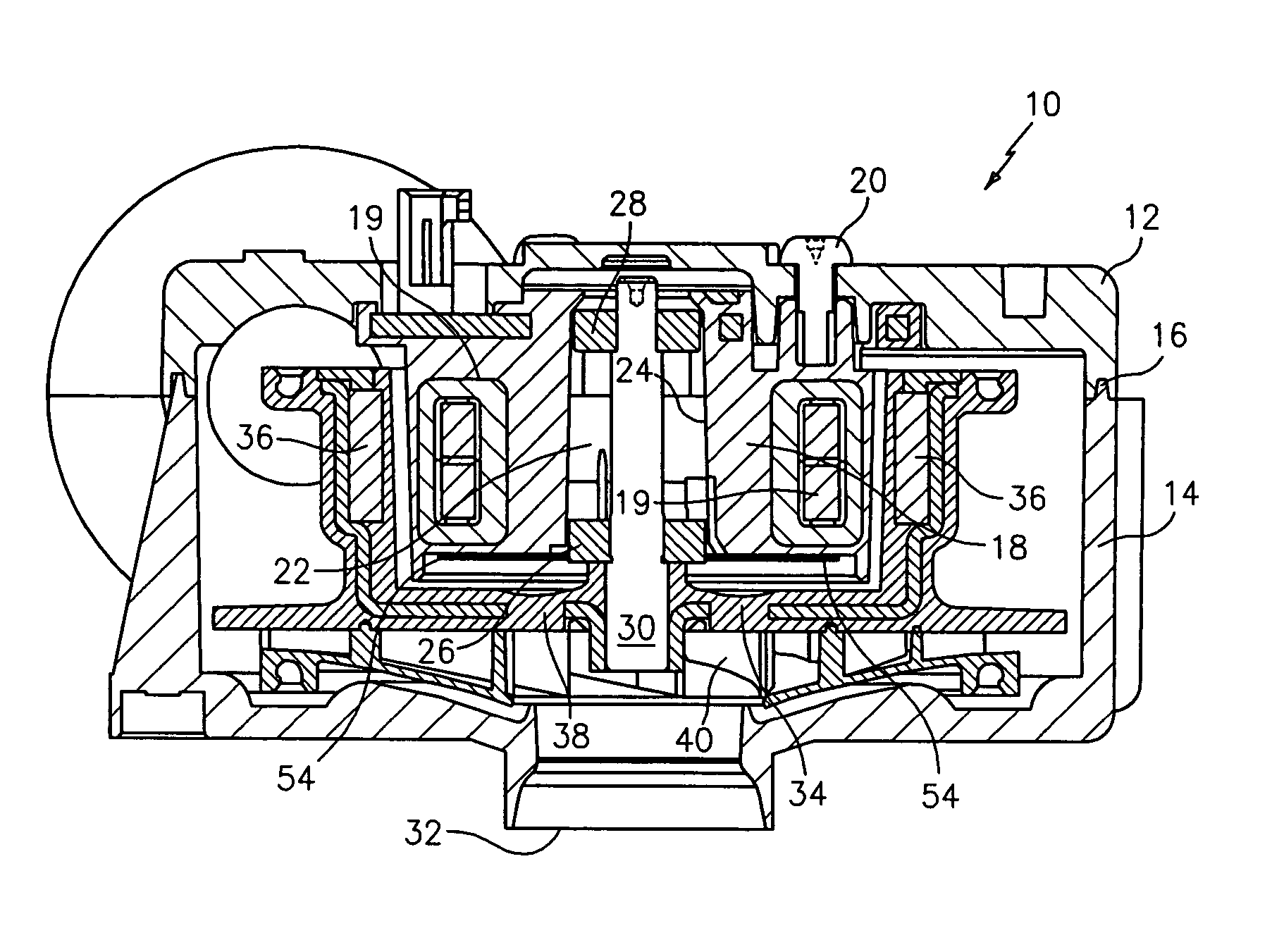
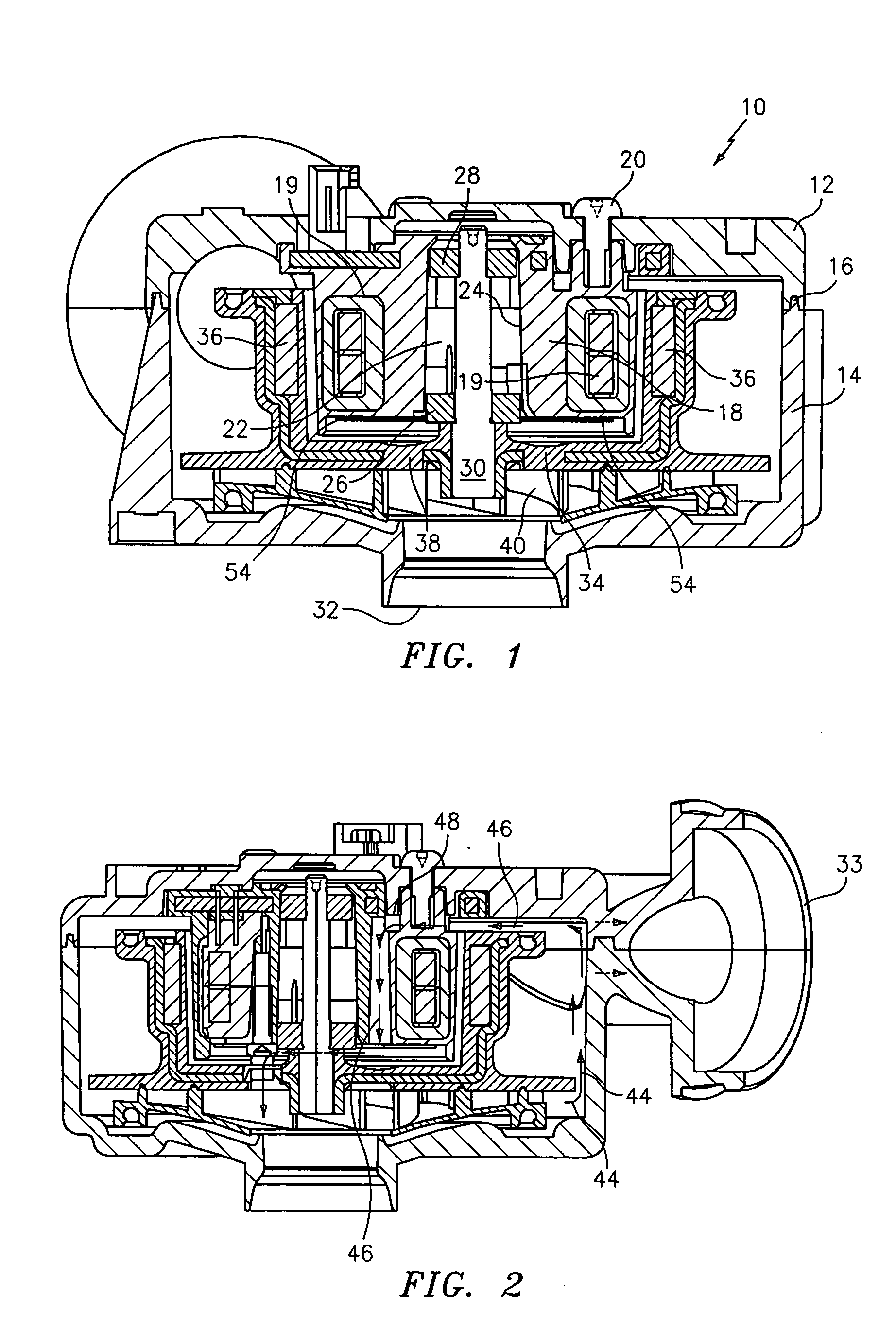
[0016] Referring to FIG. 1, a low part count blower-motor assembly is indicated generally at 10 and includes upper and lower parts 12 and 14. The parts are adapted for snap-fit engagement at a tongue and groove joint 16. The upper part 12 carries a stator assembly 18 attached to the housing by screws 20, 20 (one shown) and which may be conventional or which may follow the teaching of the above mentioned U.S. application Ser. No. 10 / 679,143. The stator is tubular with annular windings at 19 and a bearing tower 22, which may be constructed in accordance with the aforementioned U.S. Application 60 / 442,407, supported in its central opening 24 in turn carries front and rear bearing units 26 and 28. The bearing units 26, 28 journal a shaft 30 which projects downwardly from the central opening of the stator toward a fluid inlet opening 32 on the lower or second housing part 14. A discharge opening is formed cooperatively by the two housings parts 12 and 14 at 33.

[0017] Supported by the st...


PUM


Abstract

A low part count blower-motor assembly in a two-part housing which defines fluid inlet and discharge openings for the blower but which is otherwise sealed when assembled. An integrated tubular stator subassembly is fixedly attached to one of the housing parts and projects axially toward the fluid inlet opening. An integrated motor rotor subassembly is also disposed within the housing for rotation about the stator subassembly in coaxial relationship therewith, a part of the rotor subassembly being disposed axially between the stator and the inlet opening in spaced relationship with the opening. A shaft is journaled in the central opening of the tubular stator subassembly and projects axially there from toward the inlet opening and a fluid impeller mounted on the projecting end portion of the shaft receives fluid from the inlet opening. The impeller is also fixedly attached to the part of the rotor which resides between the stator and inlet opening.

Description

RELATED APPLICATION [0001] Provisional application No. 60 / 508,414, titled “Blower with motor sealed inside” filed Oct. 2, 2003, inventors Robert A. Hoyt, David A. Curtis and Russel H. Marvin, incorporated herein by reference.BACKGROUNG OF THE INVENTION [0002] Typical blower-motor assemblies include at least three major subassemblies, the blower or impeller, an electric motor driving the blower, and one or more housings. [0003] Part counts in these assemblies is high due primarily to the complexity of the electric motors and this of course leads to relatively inefficient assembly and manufacturing procedures. Conventionally, the motor is an external component and is connected in driving relationship with the blower by a drive shaft which passes through a blower housing. This arrangement results in high noise generation, air leakage at the shaft opening in the blower housing, air leakage through the motor bearings, and motor cooling problems if the blower is contained within an enclos...

Claims


Application Information

Patent Timeline
Patent Type & Authority Applications(United States)
IPC IPC(8): F04D25/08H02K7/14H02K9/06
CPCF04D25/082H02K9/06H02K7/14F04D29/5806
Inventor HOYT, ROBERT A.CURTIS, DAVID A.MARVIN, RUSSEL H.
Owner THE BERGQUIST TORRINGTON
Why Eureka
Try Eureka