Fuel cell voltage control

a fuel cell and voltage control technology, applied in the direction of electrical generators, emergency supply, sustainable buildings, etc., can solve the problems of fuel starvation, cost and packaging of voltage limiting use of two separate and distinct auxiliary loads during startup and shutdown, and avoid complex fuel inlet manifold designs, simple, low cost and more effective packaging

Active Publication Date: 2005-04-07
AUDI AG
View PDF5 Cites 36 Cited by
  • Summary
  • Abstract
  • Description
  • Claims
  • Application Information

AI Technical Summary

Benefits of technology

[0019] Objects of the invention include: avoiding complex fuel inlet manifold designs; simpler, lower cost and more effective packaging of voltage limiting devices for a fuel cell stack; use of a single voltage limiting auxiliary load for both startup and shutdown of a fuel cell stack; precise control over fuel cell stack voltage, during startup and shutdown; fuel cell stack voltage limiting that is tuneable to the startup and shutdown characteristics of individual fuel cell stacks, and tuneable to the variations in fuel cell stack characteristics across the operating life of each fuel cell stack; a voltage limiting capability which

Problems solved by technology

There are several problems with the prior art fixed auxiliary load voltage limiting function described hereinbefore.
If the same auxiliary load is used both for startup and shutdown, then either startup, shutdown or both will not be optimized as a result.
The use of two separate and distinct auxiliary loads for voltage limiting during startup and shutdown are costly to implement and package.
If current is drawn through a cell which does not have adequate fuel, the result is called “fuel starvation” which creates the negative voltages in an individual cell with inadequate fuel.
This results in many individual cells rising to a voltage level greater than that at which unde

Method used


Image

  • Fuel cell voltage control
  • Fuel cell voltage control
  • Fuel cell voltage control

Examples


Embodiment Construction

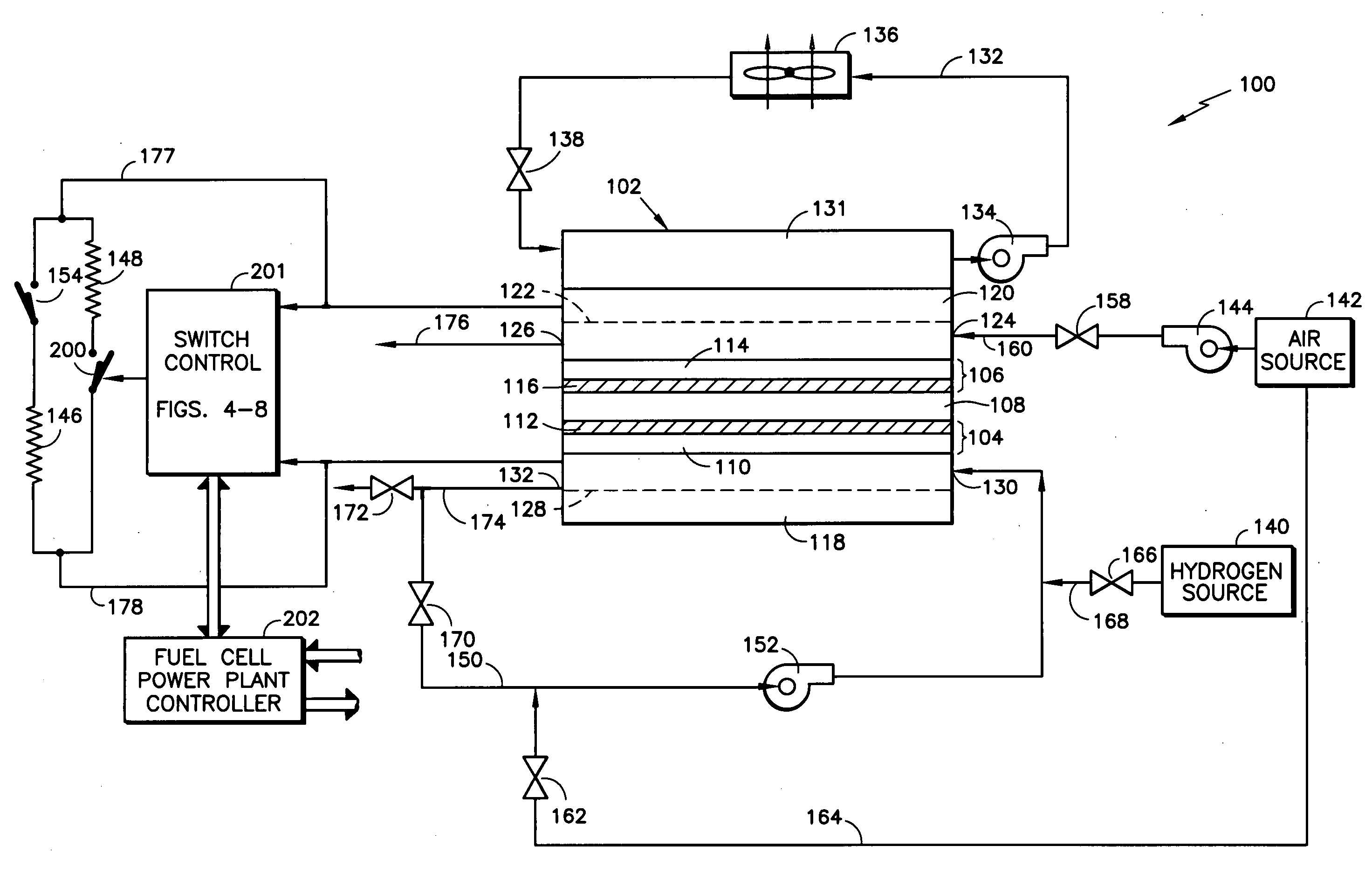
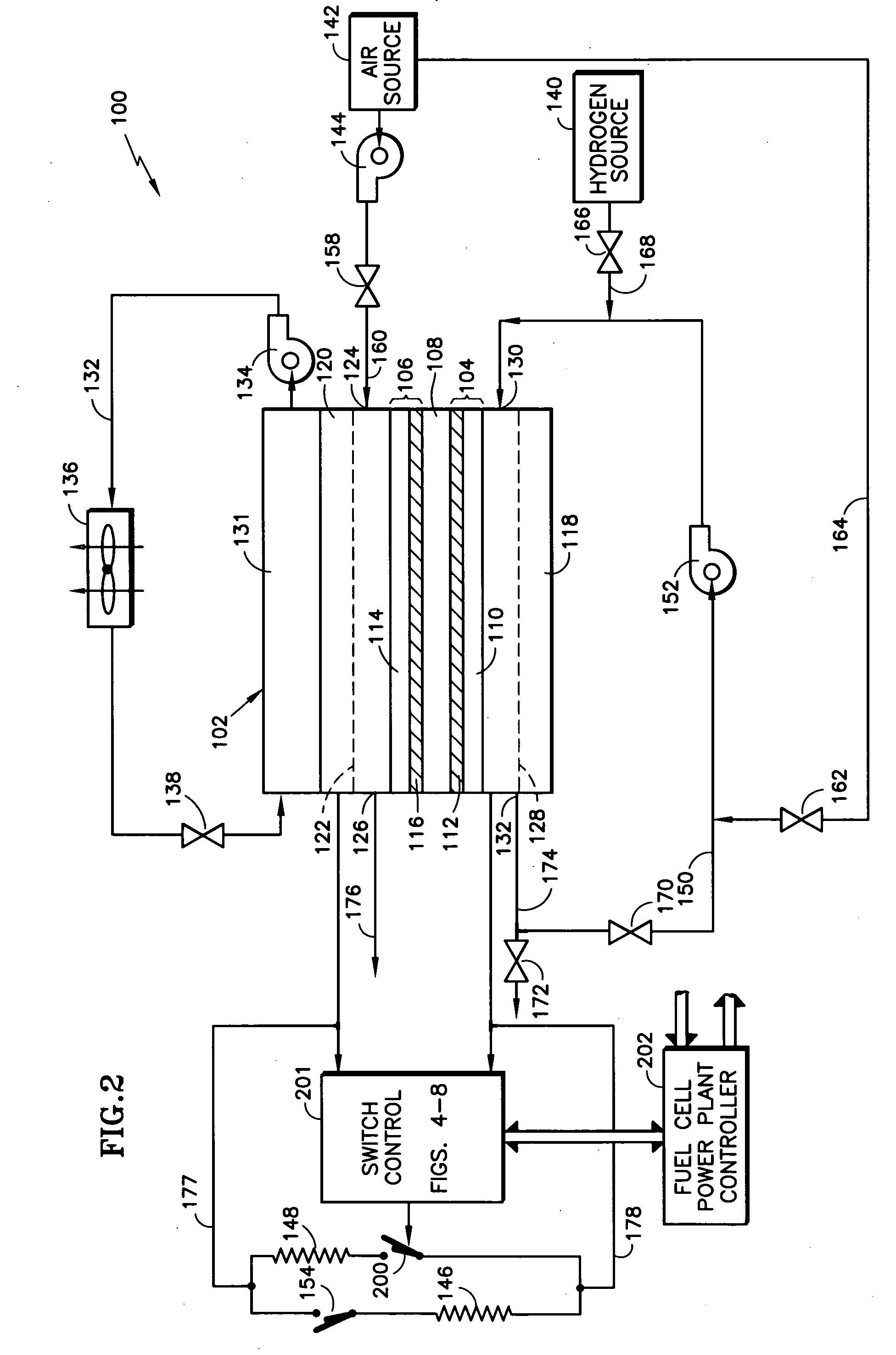
[0033] Referring to FIG. 2, in accordance with the invention, a switch 200 is operated cyclically during fuel cell stack startup and during fuel cell stack shutdown, in response, at least, to the stack voltage between the external circuits 177, 178. A switch control 201 can take a variety of configurations which are illustrated in FIGS. 4-8. Various functions, such as enabling startup and shutdown procedures, are controlled by a processor based controller 202.

[0034] A first configuration of the switch control 201 (as illustrated in FIG. 3) closes the switch 200 when the average voltage per cell in the stack reaches an upper limit 203, which may be on the order of 0.33 volts. The resultant current flow causes the voltage to decrease; and when the voltage decreases to a lower limit 204, which may be on the order of 0.13 volts, the switch 200 is once again opened.

[0035]FIG. 4 is a simplified illustration of comparators 205, 206 comparing the cell stack voltage on the line 177 with an...


PUM


Abstract

An auxiliary load (148) for a fuel cell stack (102) is alternatively connected and disconnected from the fuel cell external circuit (177, 178) by a switch (200) in response to a switch control (201), repetitively, during startup and shutdown. The switch may be an insulated gate bipolar transistor (208) which is turned on and off by hunting between an upper limit voltage (207) and a lower limit voltage (208), which may be performed by compare circuits (205, 206), by the controller (202), or by commercially available voltage responsive hysteresis switches. Schedules of duty cycle as a function of cell stack voltage for startup (212) and shutdown (213) control a pulse width modulator (215) which operates the switch. Controls (229, 231) may limit the modulation so that the auxiliary load does not overheat, in response to temperature (221) of the load or a voltage/power model (235). The auxiliary load may comprise a heater in a water accumulator (247), an air intake (257) or an enthalpy recovery device (262).

Description

TECHNICAL FIELD [0001] This invention relates to a voltage limiting auxiliary load of a fuel cell stack which is periodically engaged in a fashion to simulate a load of a desired magnitude, optionally with temperature control, and in which the auxiliary load also provides heat to the stack, such as air or coolant, or to an oxidant energy recovery device. BACKGROUND ART [0002] U.S. patent application Ser. No. 10 / 305,301 filed Nov. 26, 2002 discloses the use of an auxiliary load selectively attached to the electrical output of a fuel cell stack to limit individual cell voltage resulting from introduction of reactants during startup and resulting from consumption of reactants during shutdown of the fuel cell power plant, as described with respect to FIG. 1. [0003] In FIG. 1, a prior art fuel cell system 100 includes a fuel cell 102 comprising an anode 104, a cathode 106, and an electrolyte layer 108 disposed between the anode and cathode. The anode includes an anode substrate 110 havin...

Claims


Application Information

Patent Timeline
IPC IPC(8): H01MH01M8/04
CPCH01M8/04014H01M8/04029H01M8/04037H01M8/04097H01M8/04231H01M8/04238Y02E60/50H01M8/0432H01M8/04335H01M8/04358H01M8/04955H01M2250/10Y02B90/14H01M8/04268Y02B90/10H01M8/04
Inventor SKIBA, TOMMYJAYNE, DAVID D.GRUBB, PAUL A.GROVER, RISHIREMMERS, TIMOTHY M.SEDLACEK, WESLEY E. JR.
Owner AUDI AG
Why Eureka
Try Eureka