Method for manufacturing aluminum heat exchanger

a technology of heat exchanger and aluminum, which is applied in the direction of manufacturing tools, soldering devices, light and heating equipment, etc., can solve the problems of difficult to reduce the thickness of aluminum materials, reducing the mechanical strength of aluminum materials,

Inactive Publication Date: 2005-04-14
DENSO CORP
View PDF11 Cites 28 Cited by
  • Summary
  • Abstract
  • Description
  • Claims
  • Application Information

AI Technical Summary

Benefits of technology

[0009] The present invention has been made to solve the above-mentioned problems and an object thereof is to provide a manufacturing method capable of favorably carrying out the brazing of an aluminum heat exchanger by only one heating.

Problems solved by technology

As the mechanical strength of aluminum material is lowered due to such a thermal history, it is difficult to reduce the thickness of aluminum material.

Method used


Image

  • Method for manufacturing aluminum heat exchanger
  • Method for manufacturing aluminum heat exchanger

Examples


first embodiment

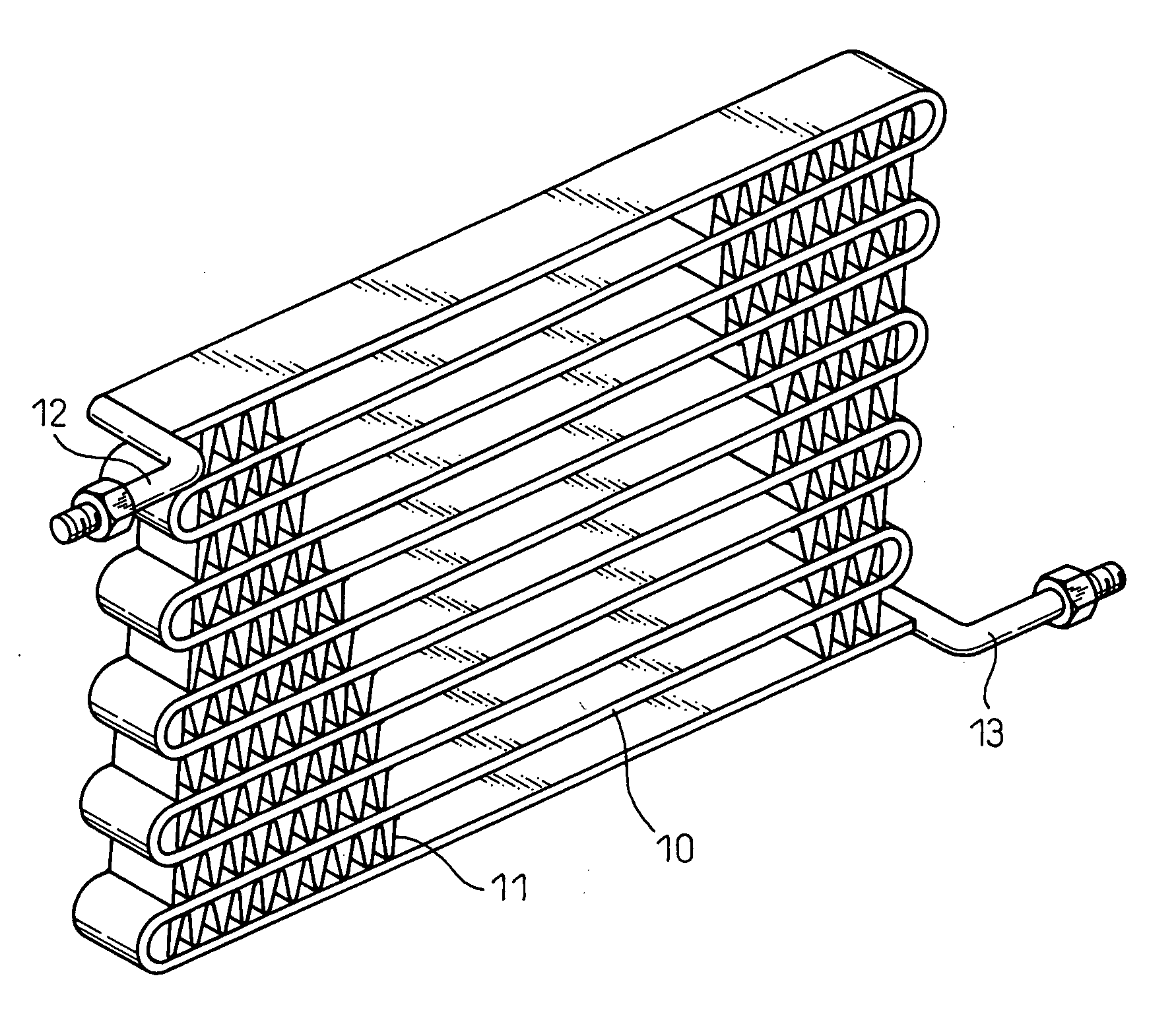
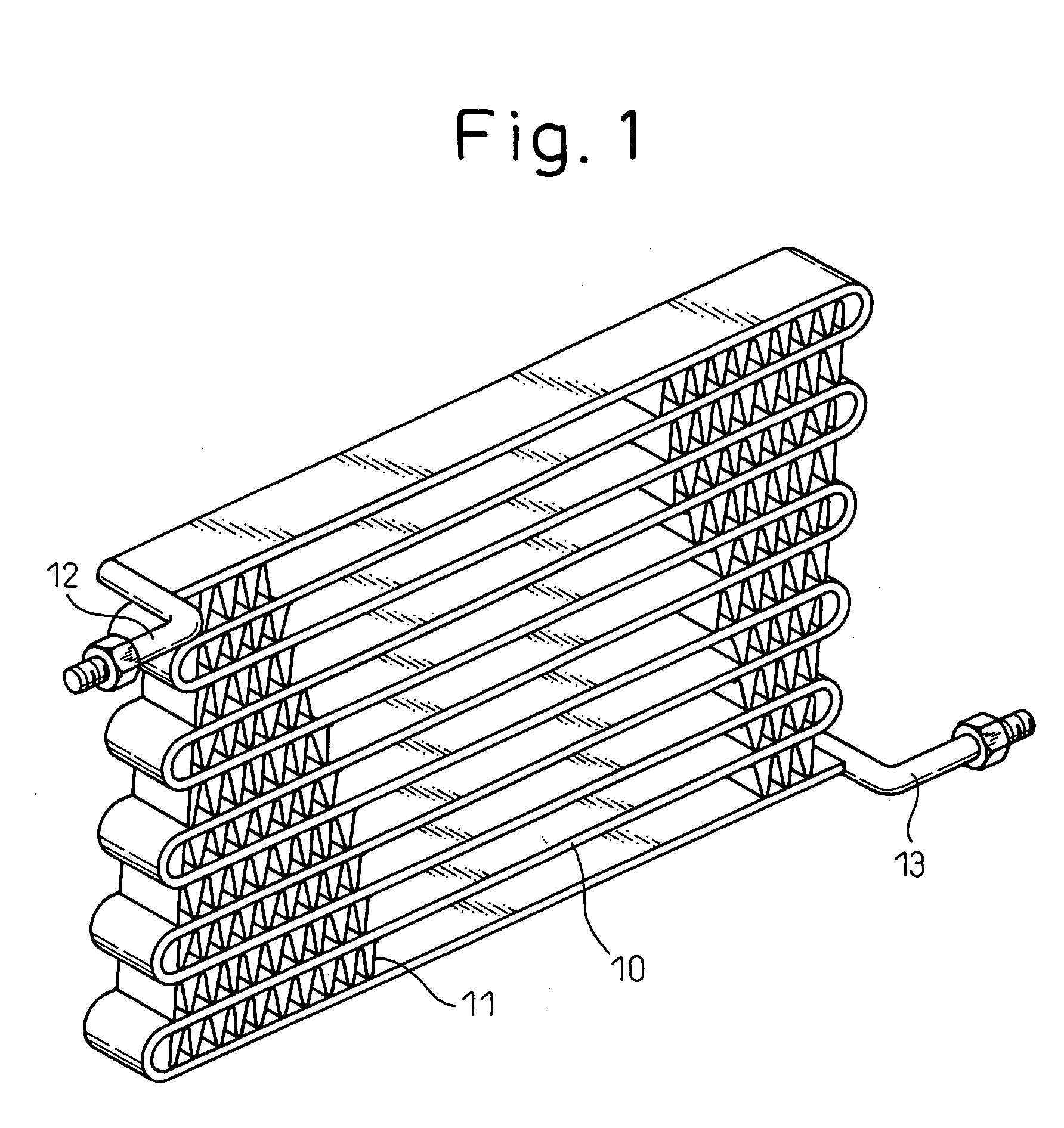
[0045]FIG. 1 illustrates a refrigerant condenser for a car air conditioner which is one example of an aluminum heat exchanger manufactured by a first embodiment of the inventive method.

[0046] The coolant condenser shown in FIG. 1 has a tube 10 forming a refrigerant passage through which flows highly pressurized refrigerant. The tube 10 is a flat multi-passage tube. As is well-known, the flat multi-passage tube is made by the extrusion molding of aluminum material to have a plurality of refrigerant passages arranged parallel to each other in cross-section. The tube 10 is bent in a zigzag manner to form a plurality of parallel pieces continuously joined together so that a predetermined gap is formed between the adjacent pieces.

[0047] A corrugated fin 11 is inserted between every adjacent parallel piece of the tube bent in a zigzag manner and is bonded to the pieces. This corrugated fin 11 is formed by bending a thin aluminum sheet in a corrugated manner. A refrigerant inlet pipe 12 ...

second embodiment

[0075] In the first embodiment, the aluminum members such as a tube 10, fins 11 or refrigerant inlet / outlet pipes 12, 13 are assembled to form an assembly of a predetermined structure and then the powder mixture of brazing material and flux is applied to the surface of the assembly. Contrarily, in a second embodiment, the powder mixture of brazing material and flux is applied solely to the surface of the extrusion-molded tube 10.

[0076] The powder mixture used in the second embodiment may be the same as used in the first embodiment. However, as the tube 10 must be bent in a zigzag manner after the powder mixture of brazing material and flux has been applied, the powder mixture is liable to peel off from the tube during the bending process.

[0077] Accordingly, in the second embodiment, a binder, for imparting a suitable viscosity, such as a paint is added to a solution of the powder mixture of brazing material and flux to form a binder-containing mixture compound. The binder-containi...


PUM

PropertyMeasurementUnit
temperatureaaaaaaaaaa
melting pointaaaaaaaaaa

Abstract

A mixture of a low-temperature active-type non-corrosive flux and a low-melting point brazing material consisting of zinc, or zinc-aluminum alloy mainly composed of zinc, is applied to at least one 10 of a plurality of aluminum members 10 to 13, and the plurality of aluminum members 10 to 13 are brazed with each other by heating an assembly of the plurality of aluminum members 10 to 13 at a temperature exceeding a melting activity-initiating point of the non-corrosive flux and a melting point of the low-melting point brazing material.

Description

BACKGROUND OF THE INVENTION [0001] 1. Field of the Invention [0002] The present invention relates to a method for manufacturing an aluminum heat exchanger, formed by brazing a plurality of aluminum members to each other, which is suitably used for a refrigerant condenser, a refrigerant evaporator of a car air-conditioner, a hot water type radiator (a heat core) for heating or a cooling water radiator of a car engine. [0003] 2. Description of the Related Art [0004] In Japanese Unexamined Patent Publication No. 62-84868, a method is disclosed for carrying out the brazing of aluminum heat exchanger by using a brazing material, having a low melting point, such as zinc or zinc-aluminum alloy. Concretely, a fluoride type non-corrosive flux is applied to a surface of a tube of the aluminum heat exchanger. Thereafter, the tube is preheated to a temperature in a range from 100 to 200° C. and then the brazing material having a low melting point, such as zinc or zinc-aluminum alloy is applied ...

Claims


Application Information

Patent Timeline
Patent Type & Authority Applications(United States)
IPC IPC(8): B23K1/00B23K1/19F28F9/18B23K35/28B23K35/36B23K35/363B23K101/14F28D1/047F28F21/08
CPCB23K1/0012B23K35/282B23K35/3605B23K2201/14Y10T29/4935F28D1/0478F28F21/084Y10T29/49393B23K2203/10B23K2101/14B23K2103/10
Inventor KANADA, KENSO
Owner DENSO CORP
Why Eureka
Try Eureka