Plasma display panel

a technology of plasma display panel and plasma, which is applied in the direction of gas discharge electrode, gas discharge electrode, sustain/scan electrode, etc., can solve the problems of inefficiency and problematical

Inactive Publication Date: 2005-04-14
SAMSUNG SDI CO LTD
View PDF21 Cites 18 Cited by
  • Summary
  • Abstract
  • Description
  • Claims
  • Application Information

AI Technical Summary

Benefits of technology

[0014] The first electrodes include sustain and scanning electrodes formed opposite to each other, and each sustain electrode has an effective portion located inside the display area with a thickness, and a terminal portion extended from the effective portion and formed outside the display area with a thickness greater than the thickness of the effective portion.
[0015] The first electrodes have sustain and scanning electrodes formed opposite to each other, and each scanning electrode has an effective portion located inside the display area with a thickness, an interconnection portion extended from the effective portion and located close to the edge of the display area, and a terminal portion extended from the interconnection portion to the periphery of the substrate with a thickness greater than the thickness of the effective portion. The effective portion, the interconnection portion, and the terminal portion of the scanning electrode are each made to be sequentially wider.
[0016] The second electrode has an effective portion located inside the display area with a thickness, an interconnection portion extended from the effective portion and located close to the boundary of the display area, and a terminal portion extended from the interconnection portion to the periphery of the substrate with a thickness smaller than the thickness of the effective portion.
[0017] The terminal portion of the second electrode has a width smaller than the width of the effective portion, and the thickness of the electrode becomes thinner as the width of the electrode is narrowed.
[0018] The effective portion, the interconnection portion, and the terminal portion of the second electrode are each made to be sequentially narrower. The ratio d / W of the thickness of the second electrode to the width thereof is in the range of 1 / 50 to 1 / 5 for all portions of the display. The second electrode may be formed by offset printing.

Problems solved by technology

This can be problematical and inefficient as there is limited contact area to external drivers and there can be interference between neighboring lines.

Method used


Image

  • Plasma display panel
  • Plasma display panel
  • Plasma display panel

Examples


Embodiment Construction

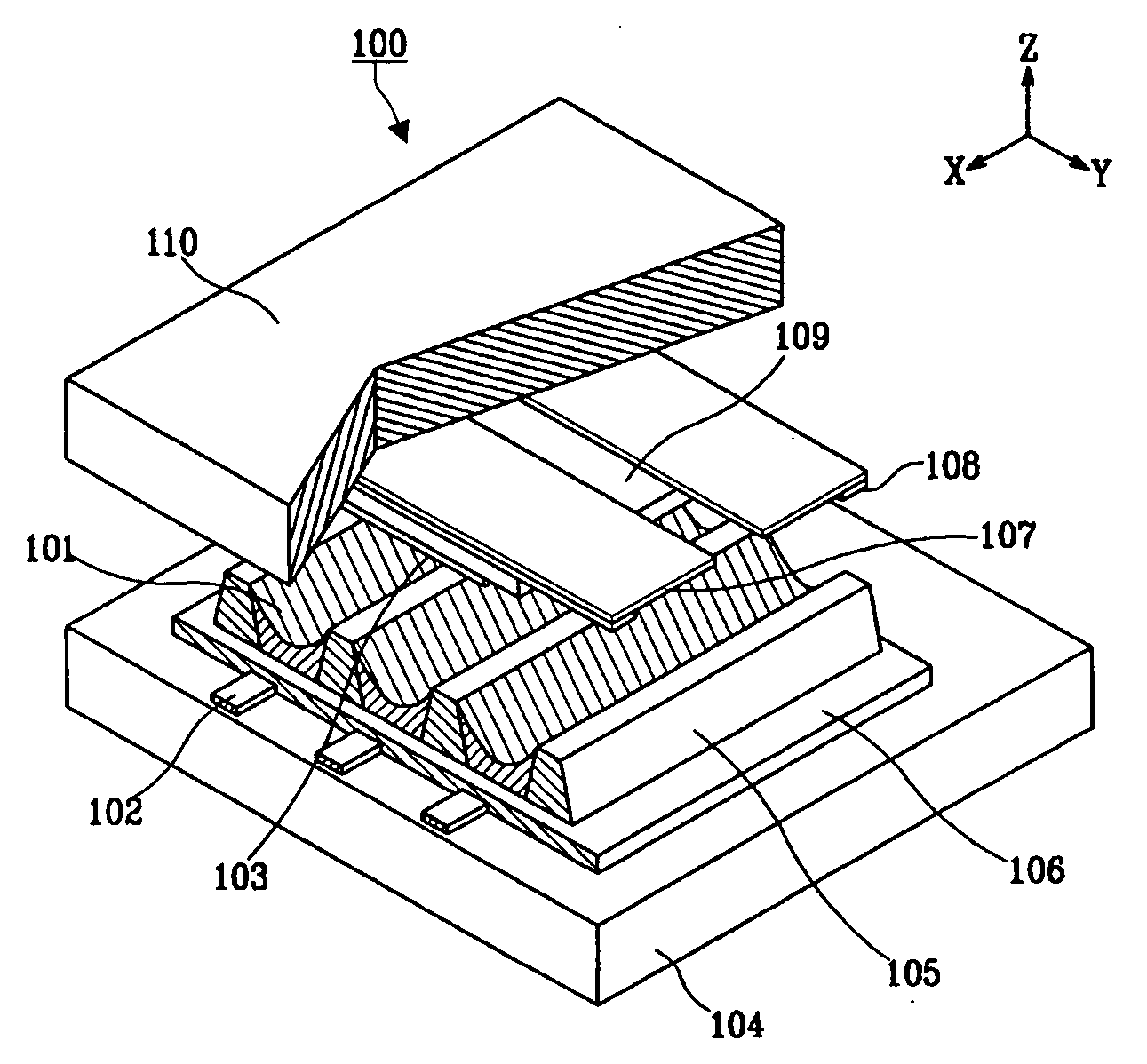
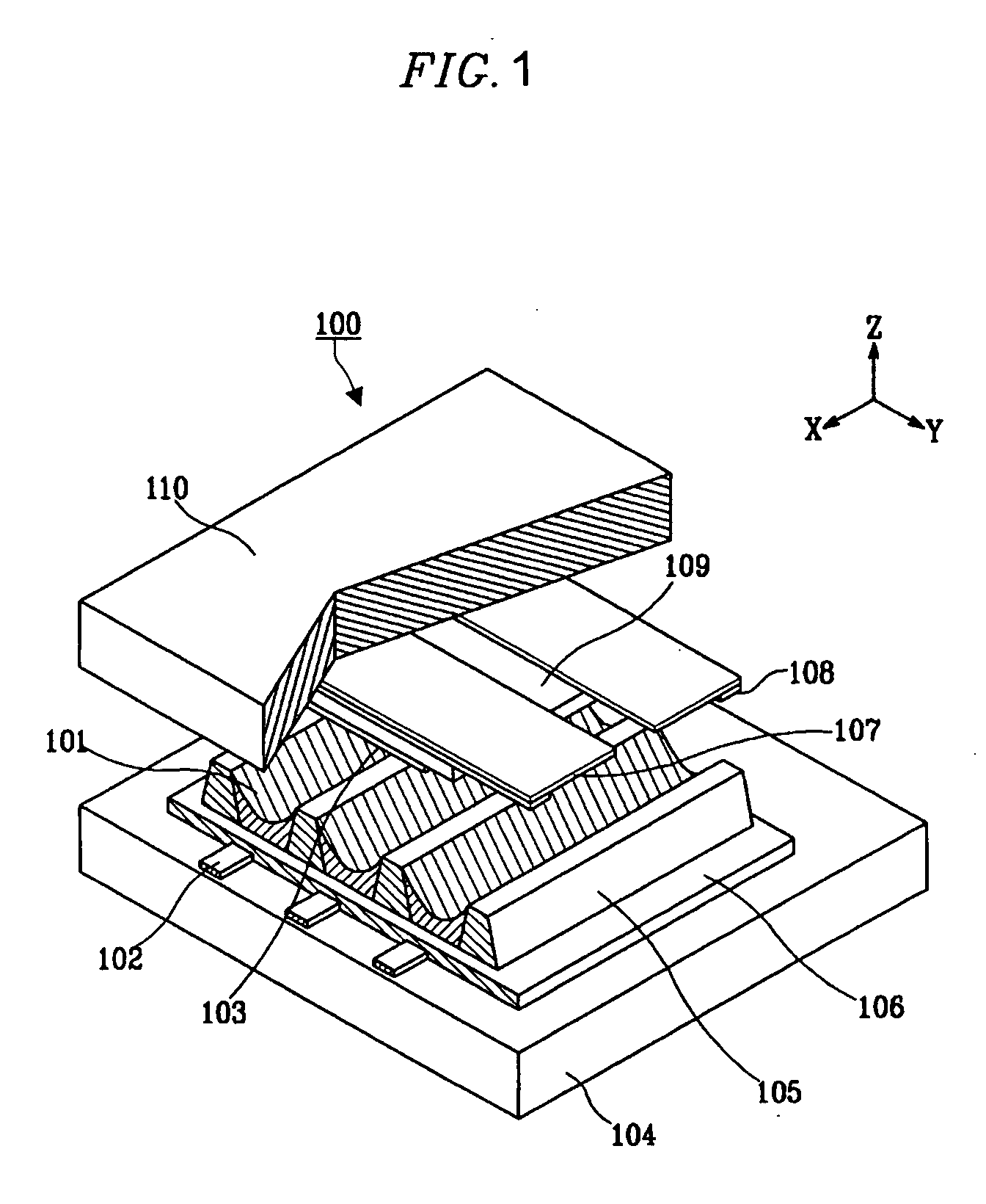
[0026]FIG. 1 is an exploded perspective view of an AC PDP 100. As illustrated in FIG. 1, the PDP 100 includes a bottom substrate 104, address electrodes 102 formed on the bottom substrate 104, a dielectric layer 106 formed on the bottom substrate 104 and covering the address electrodes 102, a plurality of barrier ribs 105 formed on the dielectric layer 106 to uphold the discharge space and prevent inter-cell cross talk, and phosphor layers 101 formed on the barrier ribs 105.

[0027] Sustain electrodes 107 and scanning electrodes 108 are formed on a top substrate 110 while proceeding perpendicular to the address electrodes 102 formed on the bottom substrate 104. A dielectric layer 109 and a protective layer 103 cover the sustain electrodes 107 and the scanning electrodes 108.

[0028] With the above-structured PDP 100, an address discharge is made between the address and the scanning electrodes 102 and 108 under the application of driving voltages thereto, thereby forming wall charges w...


PUM


Abstract

A plasma display panel that has electrode extending to a periphery thereof with a thickness and width that varies from the thickness and width of other electrode portions to enhance electrode resistance efficiency and discharge characteristics. That is, the electrodes in the display extend through a display area where visible images are generated into a non-display area around the display area where a connection to a driving circuit is made. The electrodes are designed to have varying widths and thicknesses that vary depending on whether the electrode is inside the display area or is outside the display area.

Description

CLAIM OF PRIORITY [0001] This application makes reference to, incorporates the same herein, and claims all benefits accruing under 35 U.S.C. §119 from an application entitled PLASMA DISPLAY PANEL filed with the Korean Industrial Property Office on 9 Oct. 2003 and there duly assigned Serial No. 10-2003-0070205. BACKGROUND OF THE INVENTION [0002] 1. Field of the Invention [0003] The present invention relates to a plasma display panel, and in particular, to an electrode structure at the periphery of the plasma display panel to enhance the characteristics of electrode terminals. [0004] 2. Description of Related Art [0005] Generally, a plasma display panel (referred to hereinafter simply as the “PDP”) is a display device which displays images based on plasma discharge. When voltages are applied to electrodes formed at substrates of the PDP, a plasma discharge is made between the electrodes while generating ultraviolet rays. The ultraviolet rays excite phosphor layers formed in a predeter...

Claims


Application Information

Patent Timeline
Patent Type & Authority Applications(United States)
IPC IPC(8): H01J17/04H01J17/49
CPCH01J11/12H01J2211/245H01J11/46H01J11/24
Inventor SONG, YOUNG-HWAOH, SEUNG-HEONRHO, CHANG-SEOKMOON, CHEOL-HEE
Owner SAMSUNG SDI CO LTD
Why Eureka
Try Eureka