Current starved DAC-controlled delay locked loop

Active Publication Date: 2005-04-14
ATMEL CORP
View PDF8 Cites 22 Cited by
  • Summary
  • Abstract
  • Description
  • Claims
  • Application Information

AI Technical Summary

Benefits of technology

[0012] The present invention provides a digitally controlled delay locked loop that can be shut down and rapidly restarted for the purpose of generating phase delays. This development provides a power efficient circuit having rapid lock times and restart times. This is achieved by having a lock time using a binary search.
[0014] The present invention also uses a binary search in the DAC, which provides a faster lock time than the prior art increment / decrement counters. Additionally, this binary search used in the present invention provides a fixed time for calibration, so that a lock detector circuit is not required. The multiplexing delay chain between lock mode and free running mode saves space, reduces power requirements and allows better performance over known DLL designs.

Problems solved by technology

In the past, frequency divider circuits have been used for power consumption reduction, but not for the purpose of increasing lock-in range of the phase detector.

Method used


Image

  • Current starved DAC-controlled delay locked loop
  • Current starved DAC-controlled delay locked loop
  • Current starved DAC-controlled delay locked loop

Examples


Embodiment Construction

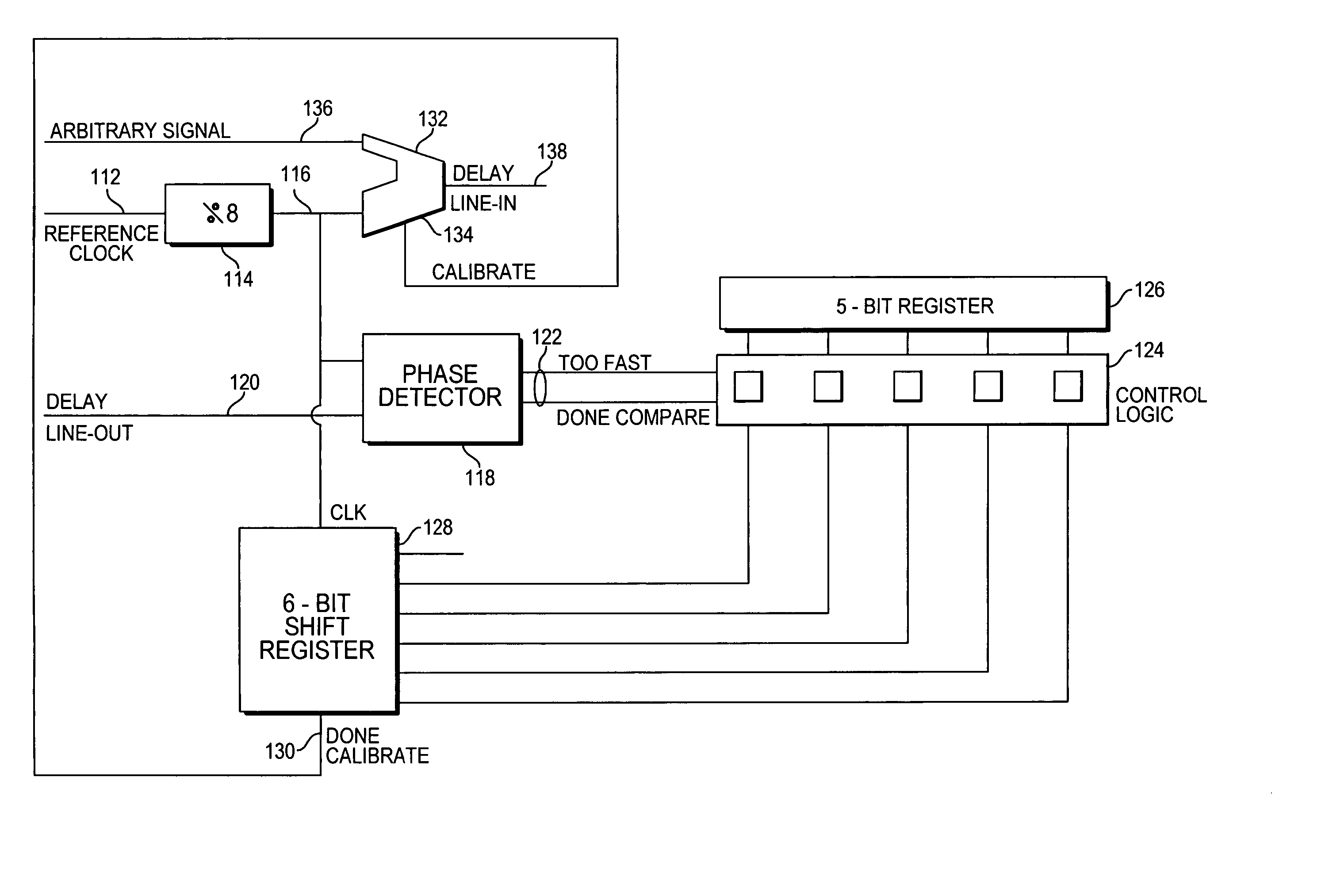
[0021] The present invention uses a digitally controlled delay locked loop to establish a fixed time through a chain of delay cells. A reference signal (for example a square wave with a period of the desired delay through the chain) is fed into the phase detector. The phase detector provides one high-going pulse to the delay chain. The detector then determines which comes first: a subsequent pulse in a reference signal or an output from the delay chain. A digital accumulator-register flips states based on a result of the proceeding determination. The accumulator register feeds a digital analog converter that provides a current reference for the delay chain.

[0022] The present invention proves several design features that provide improved performance over the prior art. The phase detector sends, for example, one in eight pulses to the delay chain. This removes any possibility of locking to the wrong response since the delay chain will not currently have a pulse in it when a pulse is ...


PUM


Abstract

A delay locked loop circuit with improved restart features. The circuit includes a clock input, a clock output, a divider circuit, phase detector and control logic. The circuit includes a means for implementing a binary search of outputs from the control logic for generating a calibration bit, which is applied to the transmission on an output line.

Description

CROSS-REFERENCE TO RELATED APPLICATION [0001] This application claims priority from U.S. provisional application no. 60 / 510,739, filed Oct. 10, 2003.TECHNICAL FIELD [0002] The present invention relates to semiconductor circuits, and more specifically to an improved delay locked loop (DLL) design for power conservation and rapid shut down and restart. BACKGROUND ART [0003] The design of current starved delay cells is relatively well known in the art. A pair of cascading CMOS inverters, with an additional p- and n- channel transistor inserted into the current path and mirrored from a reference current will establish a fixed delay through a cell. However traditional current-starved DLL designs have a number of drawbacks. The current values must be exact and must match the delay circuit. Short delays for an input signal require high operating current. To compensate for other variations, such as voltage supply or temperature variations, requires high value current mirrors. These features...

Claims


Application Information

Patent Timeline
Patent Type & Authority Applications(United States)
IPC IPC(8): H03L7/081H03L7/107
CPCH03L7/0814H03L7/1077H03L7/107H03L7/0816
Inventor MEYER, DANIEL J.
Owner ATMEL CORP
Why Eureka
Try Eureka