Dc-dc converters providing reduced deadtime

Inactive Publication Date: 2005-04-14
NORTHEASTERN UNIV
View PDF5 Cites 47 Cited by
  • Summary
  • Abstract
  • Description
  • Claims
  • Application Information

AI Technical Summary

Benefits of technology

In accordance with the present invention, DC-DC power converters are disclosed that provide increased power density, reduced size, and reduced costs of manufacture. Ben

Problems solved by technology

However, because the input voltage is switched at the high frequency, the output voltage and current typically cannot be directly provided to a load in a regulated manner.
A large inductance volume normally reduces the power density of the converter.
For example, a conventional full-bridge converter has deadtime during its operation.
During the deadtime, the energy into the input is discontinuous, causing a large input current ripple.
However, the large output inductor slows the output response time.
The volume of the output inductor also takes up valuable board space.
Further, as the length of the deadtime increases, the size of the output inducto

Method used


Image

  • Dc-dc converters providing reduced deadtime
  • Dc-dc converters providing reduced deadtime
  • Dc-dc converters providing reduced deadtime

Examples


embodiment 300

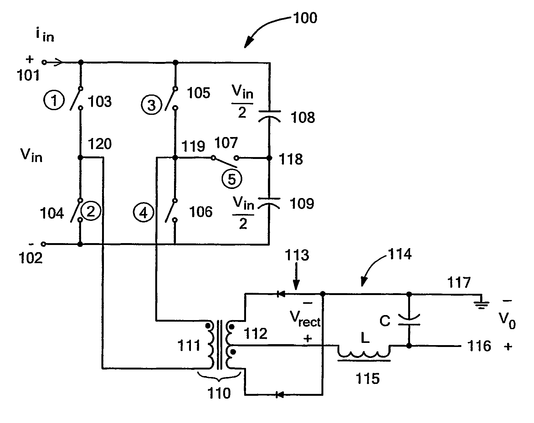
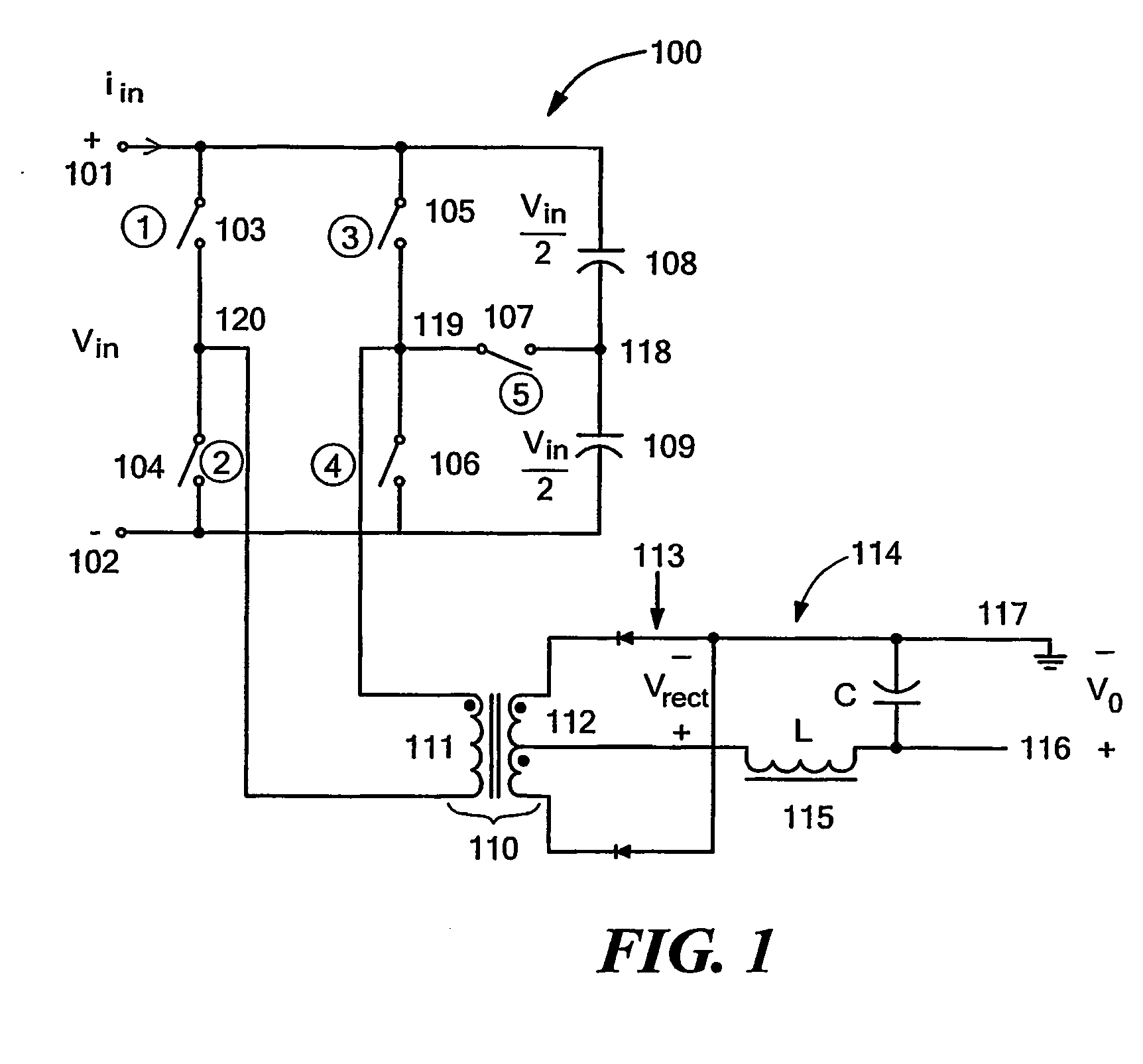
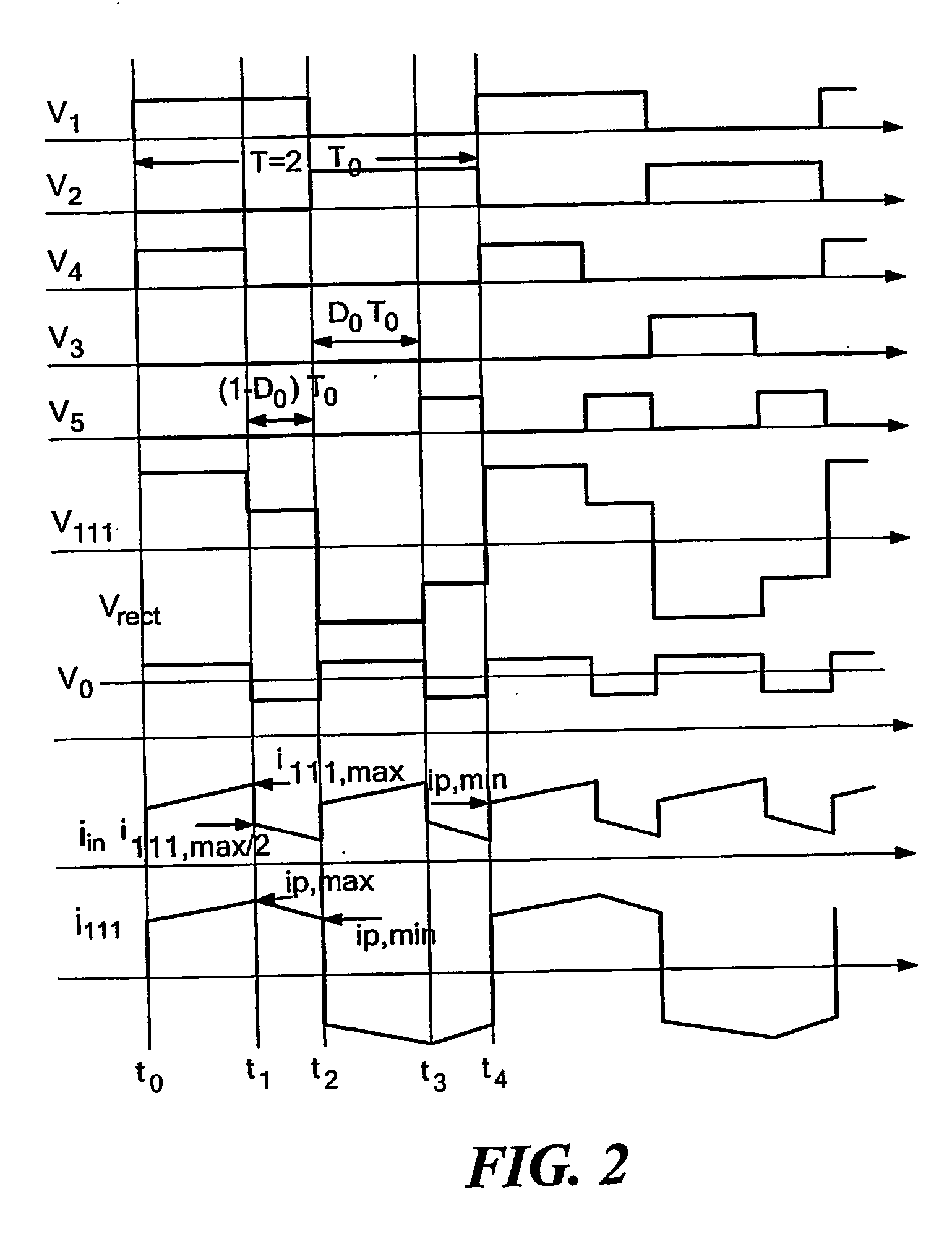
FIG. 3a depicts an alternative embodiment 300 of the DC-DC converter 100 of FIG. 1. It is noted that the ideal switching elements 103-107 of the converter100 are replaced in the DC-DC converter 300 by non-ideal MOSFET switching elements 303-307, respectively. Each of the MOSFETs 303-307 is depicted in FIG. 3a with its inherent body diode to indicate the direction of its current blocking capability when turned off. It is understood that any other suitable components may be employed for the switching elements 303-307. The DC-DC converter 300 is configured so that the switching element 107 can be controlled bi-directionally. As shown in FIG. 3a, two MOSFETs 301-302 are used to implement the function of the switching element 107. Thus, the switching element 107 is both bi-directional current carrying and bi-directional blocking. The switching elements 303-306 operate at the same frequency. The switching element 303 is off when the switching element 305 is on (see the waveforms for contr...

embodiment 400

FIG. 4 depicts a second alternative embodiment 400 of the DC-DC converter 100 of FIG. 1. In the illustrated embodiment, the DC-DC converter 400 has the Zero Voltage Switching (ZVS) property. Although the control signals V1-V4 and V6-V7 of the converter 400 are not phase shift signals, the ZVS property can be obtained via the proper time selection of the control signals V1-V4 and V6-V7. The ZVS property for the switching elements 301-302 is realized independently of load condition, whereas for the other switching elements 303-306, it is dependent on the load condition and the circuit parameters (as is generally the case for ZVS realization).

All of the capacitors in parallel with the switching elements 301-306 of FIG. 4 are the output capacitance, Coss, of the respective capacitors. The inductor 422, LR, utilized as a resonant inductance in the transient process, may be the leakage inductance of the transformer 110. The inductor 422 may alternatively be an external series inductance ...

embodiment 600

FIG. 6 depicts a third alternative embodiment 600 of the converter 100 (see FIG. 1) in a push-pull configuration. The DC-DC converter 600 comprises a push-pull converter including switching elements 603-604, and primary windings 613-614 of a transformer 621. The primary winding 613 and switching element 603 are connected in series across input terminals 601-602 to form a node 618. Further, the switching element 604 and the primary winding 614 are connected in series across the input terminals 601-602 to form a node 619. Moreover, electrical elements 611-612 are connected in series across the input terminals 601-602 to form a node 620. It is noted that the electrical elements 611-612 are depicted as capacitors in the presently disclosed embodiment. It is appreciated, however, that other suitable electrical elements, e.g., batteries, other DC-DC converters, or combinations thereof, may be employed. A switching element 605 connects the nodes 620 and 618, and provides a one-direction cu...


PUM


Abstract

A DC-DC power converter (100) that provides increased power density, reduced size, and reduced costs of manufacture. The DC-DC power converter (100) includes first and second input terminals (101, 102), a plurality of output terminals (116, 117), and at least one electrical element (108/109) connected to at least one of the first and second input terminals (101, 102). In the event a first voltage is applied across the first and second input terminals (101, 102), the electrical element (108/109) provides a second voltage having a value between the first voltage value and a reference voltage value. The DC-DC power converter (100) further includes a transformer (110) having a primary winding (111) and a secondary winding (112), and a switch assembly (103-107) operatively connected to the first input terminal (101), the second input terminal (102), the electrical element (108/109), and the transformer primary winding (111). In the event the first voltage is applied across the first and second input terminals (101, 102), the switch assembly (103-107) switchably applies the first, second, and reference voltages across the transformer primary winding (111) to generate at least one third voltage across the transformer secondary winding (112). The DC-DC power converter (100) further includes a rectifier (113) connected between the transformer secondary winding (112) and the output terminals (116, 117).

Description

STATEMENT REGARDING FEDERALLY SPONSORED RESEARCH OR DEVELOPMENT N / A BACKGROUND OF THE INVENTION The present invention relates generally to power converters such as DC-DC power converters, and more specifically to DC-DC power converters configured to provide reduced deadtime. DC-DC power converters are known for converting an input DC voltage into an output DC voltage having a value smaller or larger than the input voltage value, possibly with opposite polarity and / or with isolation of the input and output ground references. DC-DC converters normally accept input energy from a voltage source at a voltage input, and provide converted output energy at a voltage (and current) output, which is usually a filtered output that operates as a voltage sink. When isolation is employed in a DC-DC converter, the input voltage is typically switched on and off at a high frequency, and provided to a transformer, which provides the input / output isolation and the suitable voltage conversion. Howev...

Claims


Application Information

Patent Timeline
IPC IPC(8): H02M3/335H02M3/337
CPCH02M3/33507H02M3/3353H02M3/33569H02M3/337H02M2001/385H02M3/3374H02M2001/007H02M2001/0074H02M3/3372H02M1/0074H02M1/007H02M1/385H02M3/33573H02M3/33571H02M3/01
Inventor SONG, WEIZHU, YAN
Owner NORTHEASTERN UNIV
Why Eureka
Try Eureka