Wireless communications system

a communication system and wireless technology, applied in the field of wireless communication, can solve the problems of limited channeling effect, power consumption, and the possibility of each transceiver operating, and achieve the effect of ensuring the level of rf exposure for workers

Inactive Publication Date: 2005-04-14
INTERIOR UNITED STATES DEPT OF THE
View PDF21 Cites 27 Cited by
  • Summary
  • Abstract
  • Description
  • Claims
  • Application Information

AI Technical Summary

Benefits of technology

The wireless communications system is used to communicate in confined spaces or enclosures, such as mines, tunnels, industrial enclosures, buildings and the like. A pair of transceivers are configured to transmit and receive signals through the enclosure at frequencies ranging from 5 GHz to 15 GHz, more preferably from 8 GHz to 12 GHz, and most preferably at 10 GHz plus or minus three percent. It has been discovered, for example, that transmission at these frequencies permit transmission at distances in excess of thirteen miles through concrete lined water conveyance tunnels and that such tunnels have a limited channeling effect at these frequencies. This level of performance may be obtained in systems that transmit at a power output of 100 miliwatts, 35 miliwatts, or less, which is generally regarded as a safe level of RF exposure for workers. This level of power consumption means that each transceiver may operate for an extended period of time while being supplied by a 12 volt automotive-type battery.
In some embodiments, the transceivers are configured for duplex transmission of communications signals with built-in signal lock controls. One transceiver may transmit a call signal to the other, which detects the signal and responds with a confirmation signal indicating that the call signal was received. Receipt of the confirmation signal indicates that the recipient of the call signal was notified that the call signal arrived. Call signal detection constitutes an advantageous safety feature that is enhanced by full duplex transmission.

Problems solved by technology

It has been discovered, for example, that transmission at these frequencies permit transmission at distances in excess of thirteen miles through concrete lined water conveyance tunnels and that such tunnels have a limited channeling effect at these frequencies.
This level of power consumption means that each transceiver may operate for an extended period of time while being supplied by a 12 volt automotive-type battery.

Method used


Image

  • Wireless communications system
  • Wireless communications system
  • Wireless communications system

Examples


example 1

Signal Propagation in Azotea Tunnel

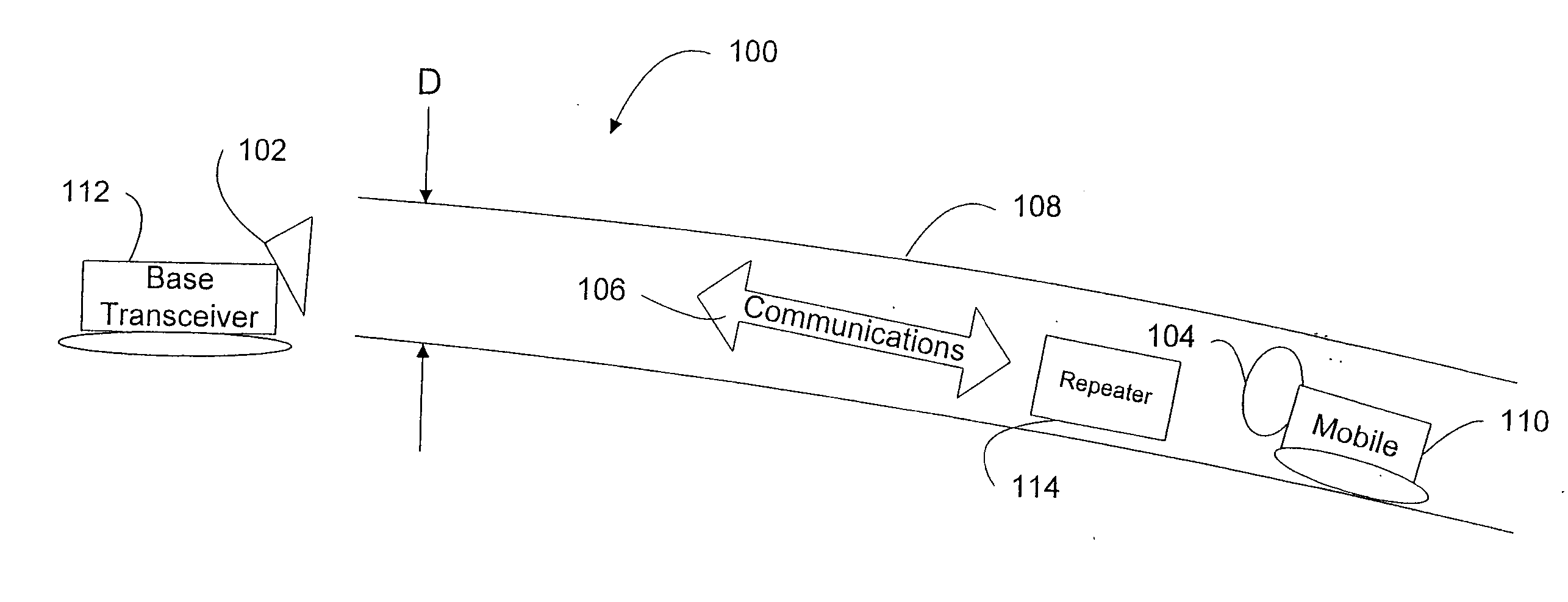
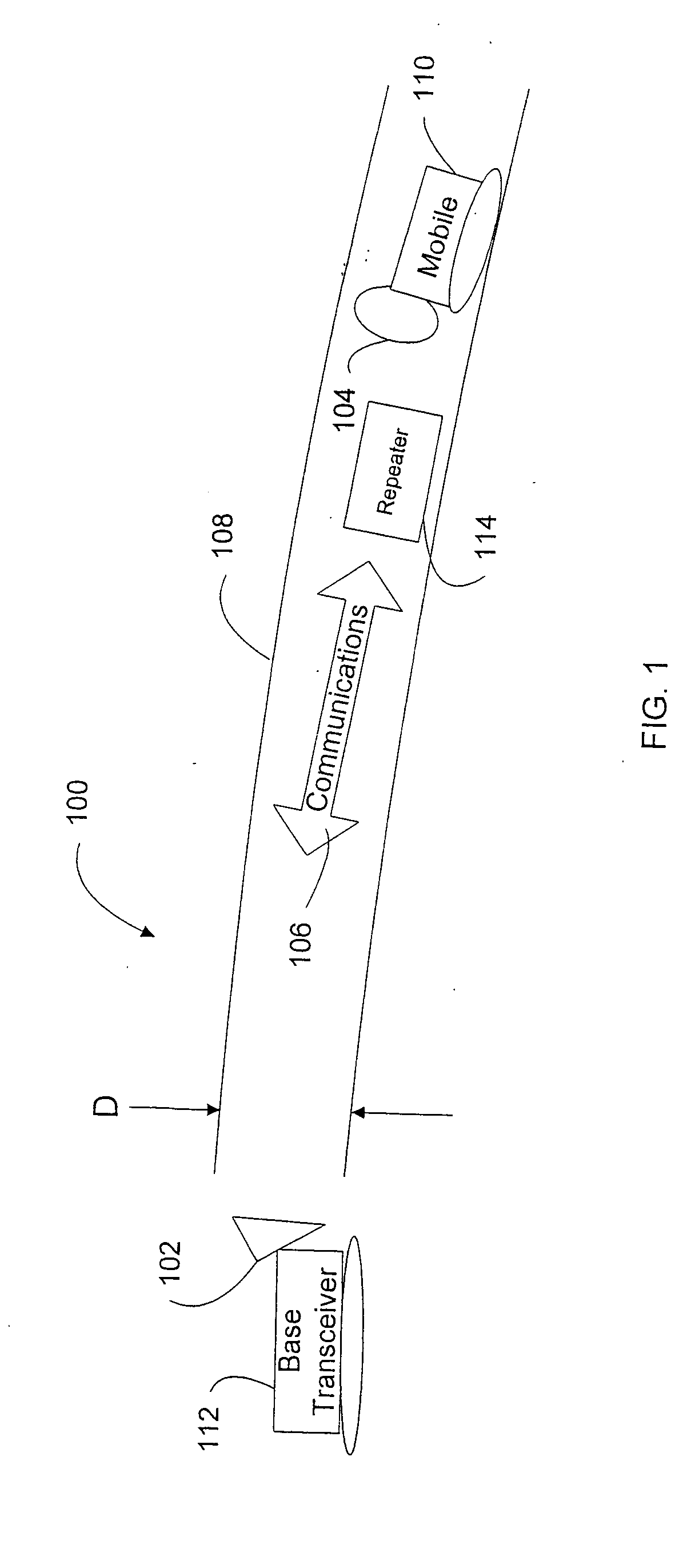
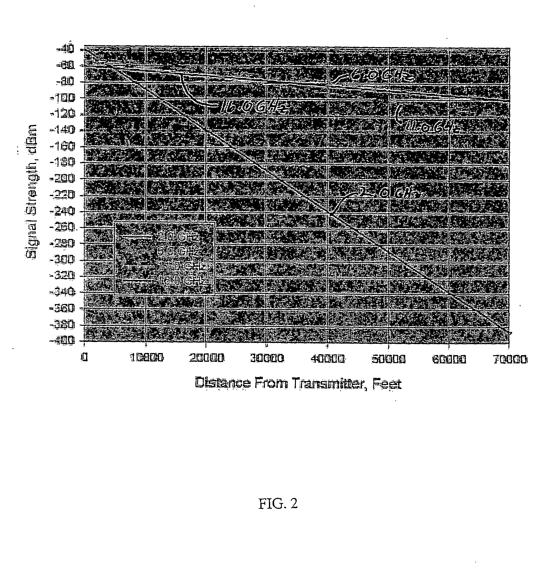
The Bureau of Reclamation operates Azotea tunnel, which is a water conveyance tunnel located near Chama, N. Mex. The tunnel is eleven feet in diameter, thirteen miles long, has a straight and uniform geometry, and is concrete lined. The water level in the tunnel was sufficiently lowered to permit access by Bureau personnel. A comparative study of signal propagation distance was performed in this tunnel. The comparative study involved: commercially available radios transmitting at 160 MHz, 400 MHz, and 900 MHz; a lossy feeder system; and a super high frequency transmitter.

Hand-held radios normally used by Bureau personnel transmitting at 160 MHz and five watts of power were found to be useless when separated by about 0.2 miles or roughly 1000 feet in Aztoea tunnel. Commercially available radios transmitting at 400 MHz and two watts of power were obtained from Safe Environment Engineering. The 400 MHz radios were effective over no more than about...

example 2

Signal Propagation in Soap Lake Siphon

The Bureau of Reclamation operates Soap Lake Siphon, which is a water conveyance tunnel located near Ephrata, Wash. The tunnel is twenty-five feet in diameter, and two and one-half miles long. The Soap Lake Siphon was selected because it has a complex geometry presenting significant changes in direction in both the vertical and horizontal planes. The Soap Lake Siphon has two different types of linings that include concrete and steel-lined concrete. FIG. 7 is a plan view of the tunnel schematic showing horizontal changes in direction. FIG. 8 is a sectional tunnel schematic showing changes in elevation in respect to a hydrologic gradient. The water level was sufficiently lowered to permit access by Bureau personnel. Soap Lake Siphon was selected for its geometry, which differs from the straight-bore Azotea Tunnel. Geometric features include: a 45° elbow 800 (FIG. 8) between points A and B; a 25° corner 700 (FIG. 7) and a 60° drop 802 (FIG. 8) ...


PUM


Abstract

A microwave communications system enhances microwave wave propagation in tunnels, mines and the like by transmitting and receiving communications signals at frequencies ranging from 5 GHz to 15 GHz. Duplex transmissions and call signal alarm functionality provide enhanced safety features for workers.

Description

BACKGROUND OF THE INVENTION 1. Field of the Invention The invention pertains to the field of wireless communications and, particularly, radio or microwave transmission systems having utility in confined spaces, such as tunnels, buildings and industrial facilities. 2. Discussion of the Related Art The United States Department of the Interior, Bureau of Reclamation, operates approximately 300 miles of water conveyance tunnels. Some of these tunnels exceed 10 miles in length. Periodically, the tunnels must be drained to provide access for maintenance operations. It is a continuing problem to provide stable communications for workers in these tunnels which, in turn, raises safety and work-efficiency issues. Wireless signal propagation is rapidly attenuated in close environments of use, such as tunnels, mines, and the like, because surrounding rock or concrete absorbs the transmissions. Accordingly, the distances over which such transmissions may occur are very limited. Commercially...

Claims


Application Information

Patent Timeline
Patent Type & Authority Applications(United States)
IPC IPC(8): H04B5/06
CPCH04B5/06H04B5/02
Inventor ATWATER, PHILIP L.DEHAAN, JAMES M.JACOBS, MALIN LESTER
Owner INTERIOR UNITED STATES DEPT OF THE
Why Eureka
Try Eureka