
Low-noise chainwheel

a chainwheel and low-noise technology, applied in driving chains, hoisting equipment, transportation and packaging, etc., can solve the problems of shifting noise, greater noise, and the inability of the chain capture tooth to fit into the narrow gap between the inner link plate, etc., to achieve the effect of eliminating or reducing the nois

Active Publication Date: 2005-04-14
SRAM +1
View PDF19 Cites 62 Cited by
  • Summary
  • Abstract
  • Description
  • Claims
  • Application Information

AI Technical Summary

Benefits of technology

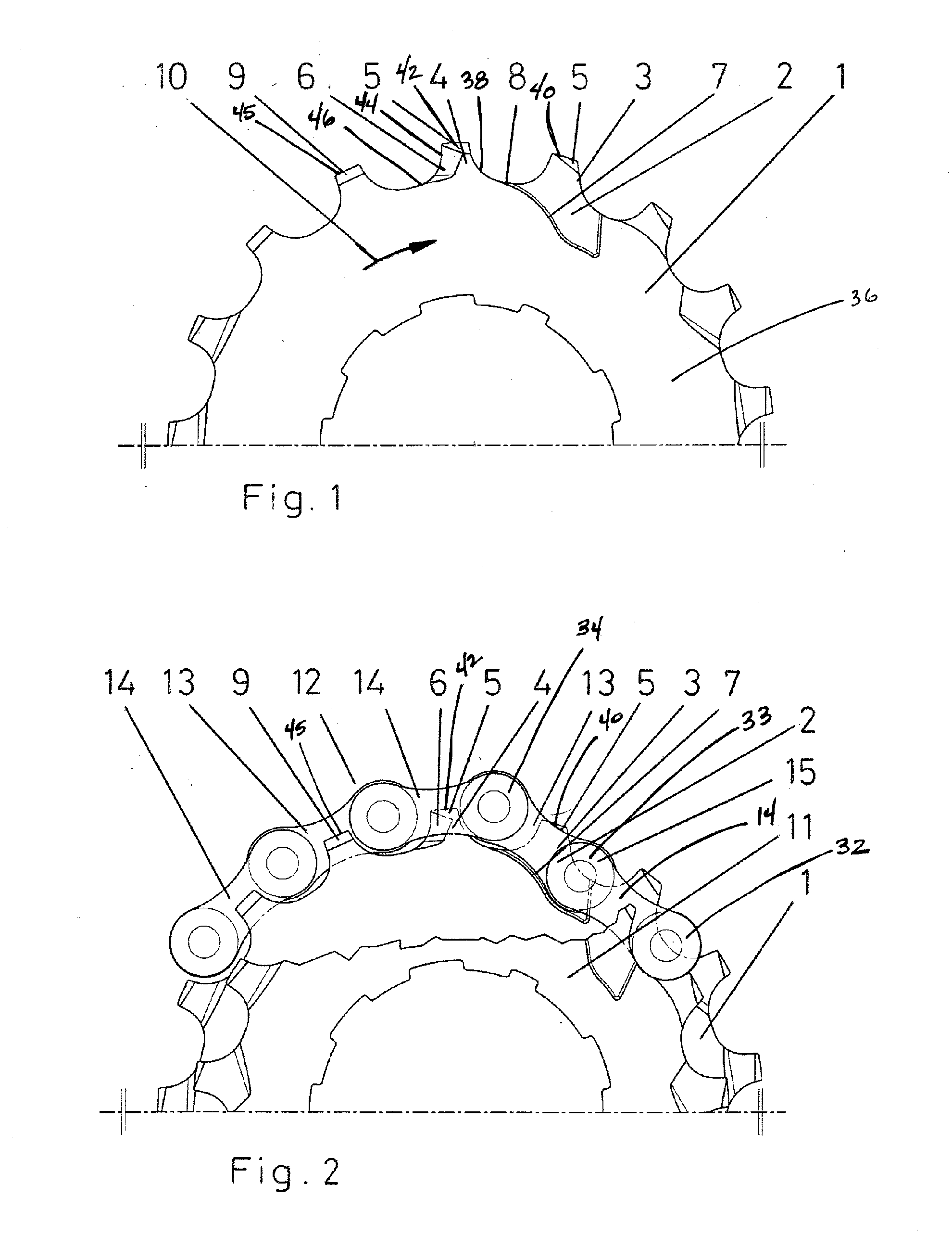
[0006] An object of the present invention is to provide a low-noise chainwheel assembly that eliminates or at least reduces the noises that occur as a tension chain segment jumps onto a larger chainwheel from a smaller chainwheel. This object is accomplished by ensuring that at the beginning of the shifting operation, the chain does not run onto a reference tooth and its following tooth. Further, the object is accomplished by ensuring that at the end of the shifting operation, the inner link plates located before the chain capture tooth come as close as possible to a back face of the larger chainwheel before the inner link plates jump over the corresponding tooth back, preventing the inner link plate from abruptly jumping over the back of the tooth located before the chain capture tooth.

Problems solved by technology

However, when a pair of inner link plates arrives at the chain capture tooth, the chain capture tooth does not penetrate into the narrow space between the inner link plates.
If a pair of inner link plates is located at the chain capture tooth, the chain capture tooth cannot fit into the narrow gap between the inner link plates.
One drawback of the above chainwheel designs is that they cause shifting noises.
When the tension segment of the chain shifts to the larger chainwheel, the chain slides up laterally on the large chainwheel and then jumps over the last tooth located before the chain capture tooth, rubbing over a back of the tooth, resulting in noise.
The greater the tension or load, the greater the angle between the chain segment sliding up laterally on the larger chainwheel tooth and the chain segment running off the larger chainwheel after the shifting operation, the greater the noise.

Method used


Image

  • Low-noise chainwheel
  • Low-noise chainwheel
  • Low-noise chainwheel

Examples


Embodiment Construction

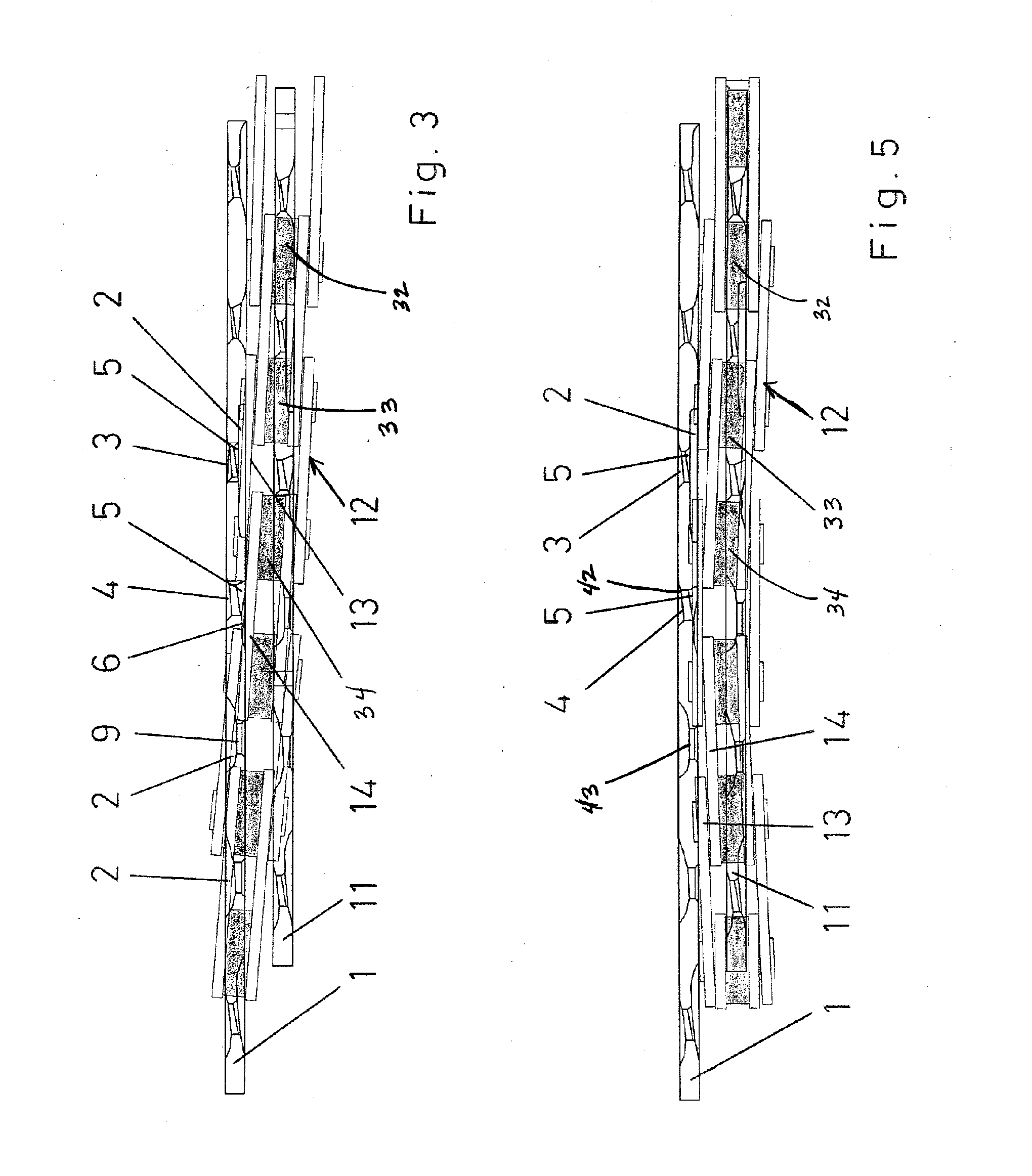
[0040]FIGS. 1-5 shows a chainwheel assembly including at least one smaller chainwheel 11 and at least one larger chainwheel 1 in accordance with one embodiment of the present invention. The chainwheels 1, 11 are engageable by a chain 12 that is made up of successive pairs of inner and outer link plates 13, 14 arranged in alternating sequence. The link plates 13, 14 are connected by pins 16 and the pins 16 are surrounded by rollers 15. The larger chainwheel 1 and the smaller chainwheel 11 are oriented relative to each other such that a distance between a center of a chain roller 34 positioned between a pair of adjacent teeth on the larger sprocket 1 and the center of a chain roller 32 between a pair adjacent teeth on the smaller chainwheel 11 is substantially an integer multiple of the chain pitch. The larger chainwheel 1 includes at least one tooth group that includes a first tooth or reference tooth 3 and a second or following tooth 4 disposed adjacent the reference tooth 3 opposit...


PUM


Abstract

A bicycle chainwheel assembly that includes at least one smaller chainwheel and at least one larger chainwheel, the chainwheels engageable by a chain. The larger chainwheel includes a first tooth and a second tooth disposed adjacent the first tooth opposite a drive rotation direction. The first tooth and the second tooth have a configuration that improves the shifting of a chain from a smaller chainwheel to the larger chainwheel. The first tooth has a lateral recess and the second tooth has a deflection chamfer. The second tooth may also have a recess. The first and second teeth have a configuration that prevents the first and second teeth from capturing the chain. An inner link plate of the chain includes a chamfer disposed on an outer side surface in a central region of the plate.

Description

BACKGROUND OF THE INVENTION [0001] The present invention relates to bicycle derailleur shifting systems and more particularly to a chainwheel assembly including a larger diameter chainwheel having at least one tooth group configured to reduce noise when shifting a chain from a smaller chainwheel to the larger chainwheel. [0002] A conventional derailleur shifting system includes a driving chainwheel assembly, a driven chainwheel assembly and a chain extending therebetween. At least one of the chainwheel assemblies includes a plurality of chainwheels having varying tooth counts. The chain includes successive pins connecting pairs of inner and outer link plates arranged in alternating sequence. A derailleur shifts the chain between chainwheels. As the chain is shifted from a smaller chainwheel to a larger chainwheel, it forms a transition region extending from a chain link that is last to engage between the two teeth of the smaller diameter chainwheel to a chain link that is first to e...

Claims


Application Information

Patent Timeline
IPC IPC(8): B62M9/10
CPCF16H55/30B62M9/10F16G13/06
Inventor REITER, MARKUS
Owner SRAM
Learn More