Honeycomb structure body and method for manufacturing the same

Active Publication Date: 2005-04-14
NGK INSULATORS LTD
View PDF2 Cites 41 Cited by
  • Summary
  • Abstract
  • Description
  • Claims
  • Application Information

AI Technical Summary

Benefits of technology

The present invention has been made in view of the above situation, and aims at providing a honeycomb structure having a high bondi

Problems solved by technology

In the honeycomb structure used for such a purpose, the sharp temperature change of exhaust gas and the local heating make non-uniform the temperature distribution inside the honeycomb structure, which has caused problems such as crack generation in honeycomb structure and the like.
When the honeycomb structure is used particularly as a filter for trapping a particulate matter in an exhaust gas emitted from a diesel engine (the filter is hereinafter referred to as DPF), it is necessary to burn the carbon particles trapped on the filter to remove the particles and regenerate the filter and, in that case, high temperatures are inevitably generated locally in the filter; as a result, a big thermal stress an

Method used


Image

  • Honeycomb structure body and method for manufacturing the same
  • Honeycomb structure body and method for manufacturing the same
  • Honeycomb structure body and method for manufacturing the same

Examples


example 1

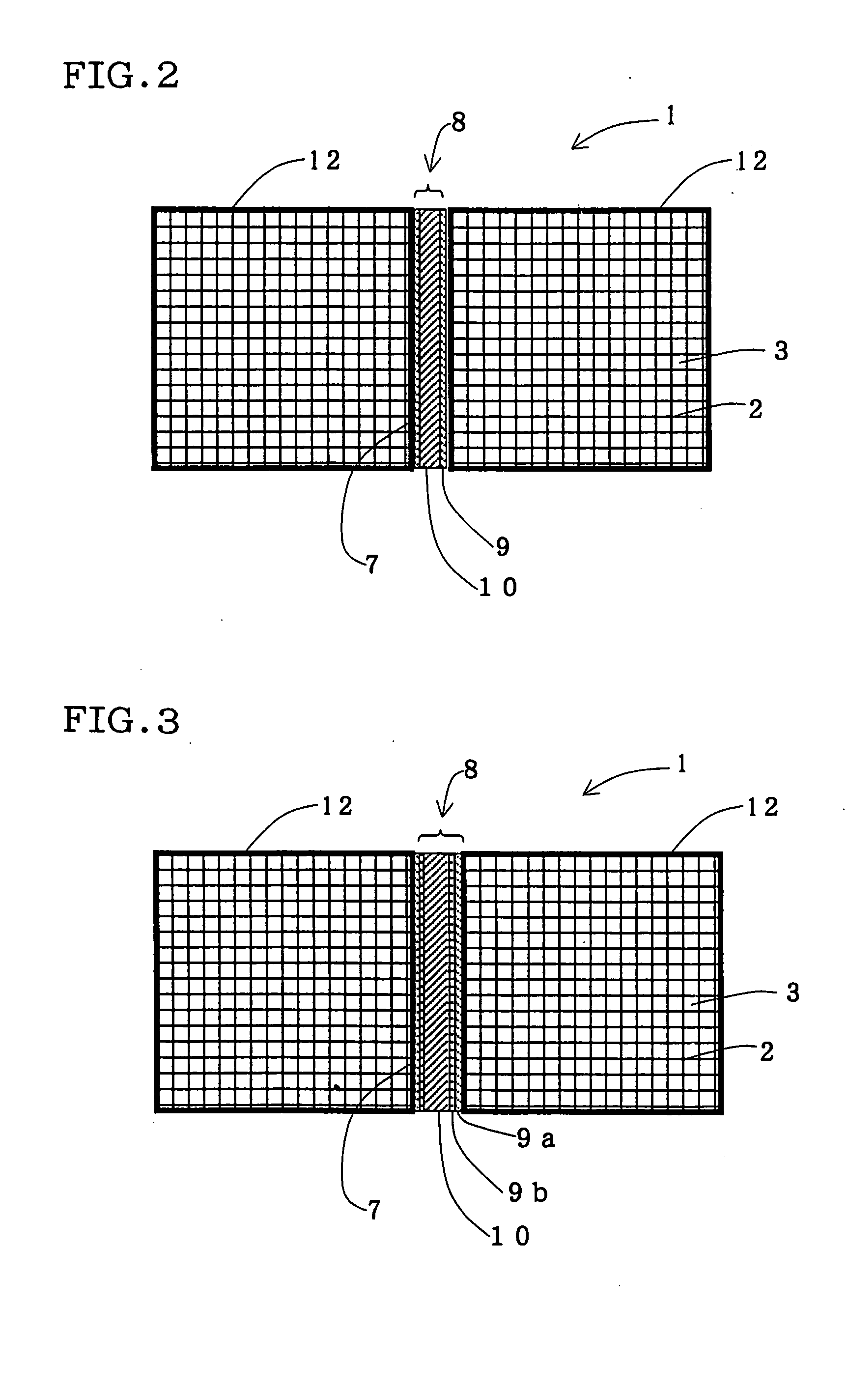
Two honeycomb segments obtained above were coated at their side walls 7 with the undercoat 1. Then, the cement was coated on the undercoat 1 on either one of the two honeycomb segments. Then, the two honeycomb segments were bonded into one piece, after which heating and drying at about 200 degree C. was conducted to obtain a honeycomb structure.

example 2

A honeycomb structure was obtained in the same manner as in Example 1 except that first the undercoat 2 was coated and then the undercoat 1 was coated on the undercoat 2 on each honeycomb segment.


PUM

PropertyMeasurementUnit
Fractionaaaaaaaaaa
Fractionaaaaaaaaaa
Fractionaaaaaaaaaa

Abstract

There is provided a honeycomb structure 1 produced by bonding a plurality of honeycomb segments 12 into one piece via a bonding layer 8, each segment 12 having a number of through-holes 3 divided from each other by porous partition walls 2 and extending in the axial direction of the honeycomb segment. The bonding layer 8 comprises at least one cement layer 10 and at least one undercoat layer 9 present between the honeycomb segment 12 and the cement layer 10. There is provided a process for producing a honeycomb structure 1, wherein bonding the honeycomb segments 12 comprises applying at least one layer of an undercoat on each honeycomb segment 12, applying at least one layer of a cement, and bonding the honeycomb segments into one piece. The honeycomb structure has a high bonding strength and hardly gives defects such as cracks in bonded portion.

Description

TECHNICAL FIELD The present invention relates to a honeycomb structure used, for example, as a catalyst carrier for an internal combustion engine, a boiler, a chemical reactor, a reformer of fuel cell or the like, or as a filter for trapping particulate present in an exhaust gas; as well as to a process for producing the honeycomb structure. The present invention relates particularly to a honeycomb structure which hardly gives defects such as cracks in bonded portion, as well as to a process for producing the honeycomb structure. BACKGROUND ART Honeycomb structures are used, for example, as a catalyst carrier for an internal combustion engine, a boiler, a chemical reactor, a reformer of fuel cell or the like, or as a filter for particulate matter present in an exhaust gas, particularly diesel particulate matter. In the honeycomb structure used for such a purpose, the sharp temperature change of exhaust gas and the local heating make non-uniform the temperature distribution inside...

Claims


Application Information

Patent Timeline
IPC IPC(8): B01D39/20B01D46/00B01D46/24B01D53/86B01D53/88B01D53/94B01J35/04B01J37/02B28B1/00C04B28/24C04B35/80C04B37/00C04B38/00F01N3/021F01N3/022F01N3/035F01N3/28F01N13/04H01M8/12H01M8/24
CPCB01D46/0001Y10T428/131B01D46/2444B01D46/2448B01D46/2459B01D53/86B01D53/885B01D53/94B01D2046/2496B01J35/04B01J37/0244B28B1/002B32B2315/02C04B28/24C04B35/565C04B35/62625C04B35/806C04B37/005C04B38/0006C04B2111/00793C04B2235/3418C04B2235/3826C04B2235/428C04B2235/5216C04B2235/80C04B2235/96C04B2235/9607C04B2237/083C04B2237/365C04B2237/72F01N3/0211F01N3/0222F01N3/035F01N3/2803F01N2450/28H01M8/2435H01M2008/1293B01D46/2429Y10T428/24165Y10T428/236Y10T428/24149Y02E60/50Y02E60/525Y10T428/24777C04B14/324C04B14/46C04B38/0019C04B35/80B01D46/2498B01D46/24494B01D46/2478Y02P70/50
Inventor FUJITA, JUN
Owner NGK INSULATORS LTD
Why Eureka
Try Eureka