Superconducting cable

a superconducting cable and cable technology, applied in the direction of superconductor devices, apiculture, capacitors, etc., can solve the problems of high bending-rigidity of pipes, complicated structure, and increase so as to reduce the heat loss of coolan

Inactive Publication Date: 2005-04-14
SUMITOMO ELECTRIC IND LTD
View PDF10 Cites 9 Cited by
  • Summary
  • Abstract
  • Description
  • Claims
  • Application Information

AI Technical Summary

Benefits of technology

[0013] It is an object of the present invention to provide a superconducting cable in which the heat loss of a coolant can be minimized and which allows the space needed for coolant piping arrangement to be compact.
[0015] In the present invention, it is possible to reduce the heat loss of a coolant flowing through the coolant return pipe because the coolant that has flown into the coolant return pipe can be cooled, by the coolant in the thermal insulation pipe, until the coolant that has flown into the coolant return pipe flows out of the thermal insulation pipe.
[0016] The coolant return pipe of the present invention may be a metal pipe having the same diameter in the longitudinal direction, or a corrugated metal pipe. When the coolant return pipe is a corrugated metal pipe, the amount of force for bending the coolant return pipe can be reduced such that mechanical damage to the cable core is prevented. In addition, since an increase in the bending rigidity of the superconducting cable can be lessened, it is possible to prevent degradation of the mechanical properties (such as the bending property and lateral pressure) of the cable.
[0018] Since the location where the coolant return pipe opens to the outside of the thermal insulation pipe is near the coolant inlet, it is possible to minimize the length of the pipe from a location where the coolant flows out of the thermal insulation pipe to a location where it returns to the refrigerator. As a result, it is possible to minimize not only the heat loss of the coolant caused outside the thermal insulation pipe, but also the space for the pipe arrangement in the vicinity of the thermal insulation pipe.
[0019] It is possible to reduce the heat loss of the coolant caused at the time of recovery thereof because the portion of the coolant piping to be disposed outside the thermal insulation pipe can be reduced since the boundary between the forward path and the backward path of the coolant channel is provided in the thermal insulation pipe which is the cable body.
[0022] In the case where the coolant outlet for taking out the coolant in the thermal insulation pipe is disposed at the other end of the thermal insulation pipe, and the other end of the coolant return pipe opens to the outside of the thermal insulation pipe from the other end of the thermal insulation pipe, the coolant return pipe may be accommodated in the thermal insulation pipe. By this, it is possible to reduce heat loss of the coolant flowing in the coolant return pipe.

Problems solved by technology

However, when a metal pipe is used as the former, the high bending-rigidity of the pipe is a problem in terms of mechanical properties, such as bending property and lateral pressure, of the superconducting cable.
However, since superconducting wires are wound around the former, it is necessary to add a structure for smoothing the outer side of the corrugated metal pipe, thereby complicating the structure.
In addition, a structure for connecting the coolant forward path in the former to the coolant backward path at the outer side of the core becomes complicated.
When such a solid former is used, a coolant channel cannot be formed in the former.
In such a coolant circulating system, the coolant flowing through the coolant outlet pipe or the coolant inlet pipe is subjected to heat loss resulting from heat exchange with ambient air outside the thermal insulation pipe.
Therefore, the outlet pipe becomes long, thereby increasing heat loss correspondingly and making it necessary to provide a wide space for disposing the outlet pipe.

Method used


Image

  • Superconducting cable
  • Superconducting cable
  • Superconducting cable

Examples


Embodiment Construction

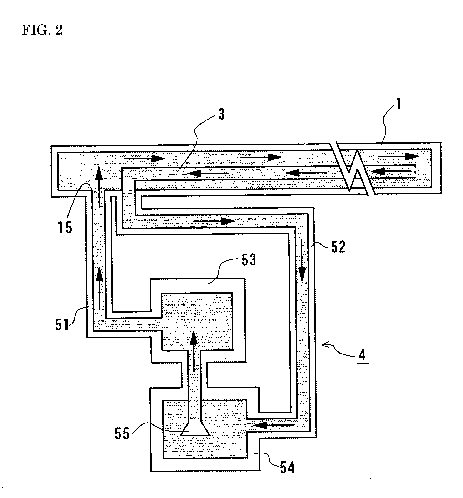
[0026] Hereunder, an embodiment of the present invention will be described. A superconducting cable of the present invention can be used as an alternating current (AC) superconducting cable or a direct current (DC) superconducting cable. Both an AC superconducting cable line and a DC superconducting cable line can be formed using the superconducting cable of the present invention.

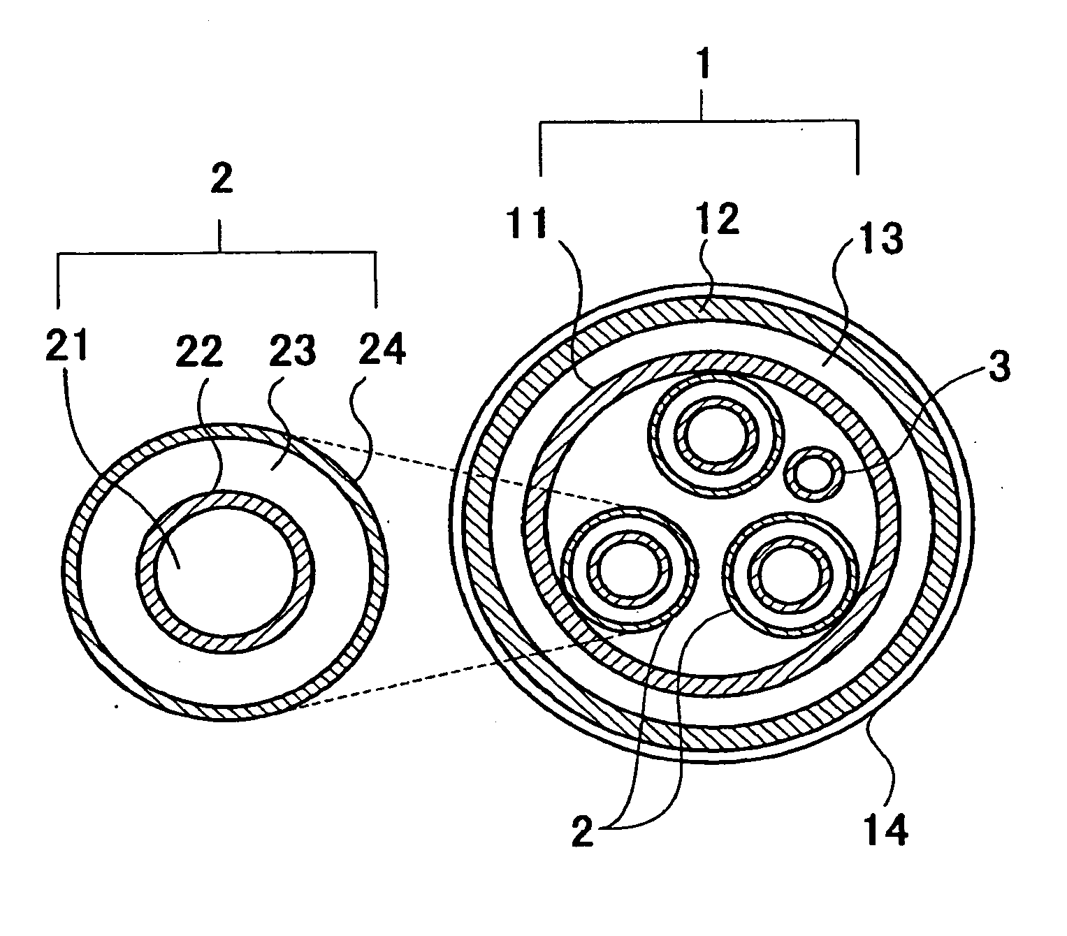
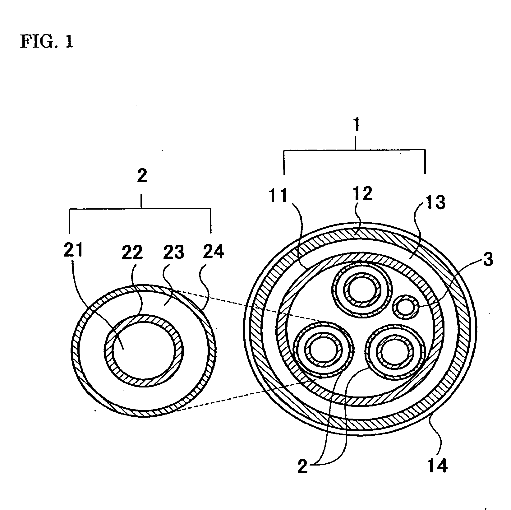
[0027] A cable core used in the present invention includes, sequentially from the center, for example, a former, a superconducting conductor, and an electrical insulation layer.

[0028] Although the former may be a solid type using metal wires stranded together or a hollow type using a metal pipe, the present invention is suitable for the solid former.

[0029] When the former is a solid type, stranded metal wires, such as stranded copper wires, may be used considering the mechanical properties of the cable. When metal wires are used, it is desirable to insulate the metal wires in order to reduce eddy current...


PUM

PropertyMeasurementUnit
superconductingaaaaaaaaaa
electricalaaaaaaaaaa
impedanceaaaaaaaaaa

Abstract

A superconducting cable includes: a cable core having a superconducting conductor; a thermal insulation pipe accommodating the cable core and functioning as a forward path of a coolant channel; and a coolant return pipe disposed beside the cable core in the thermal insulation pipe and functioning as a backward path of the coolant channel. A coolant is passed through a space formed between the thermal insulation pipe and the cable core / the coolant return pipe, and cools the cable core and the coolant return pipe. The coolant that has cooled the cable core, etc., returns through the coolant return pipe. Thus, the heat loss of a coolant in the superconducting cable can be minimized, and the space needed for coolant piping can be made compact.

Description

BACKGROUND OF THE INVENTION [0001] 1. Field of the Invention [0002] The present invention relates to a superconducting cable, and, more particularly, to a superconducting cable having a cable core whose central portion is a solid type. [0003] 2. Description of the Related Art [0004] In general, a superconducting cable is formed by putting a single cable core or cable cores, which are stranded together for providing a high capacity, into a thermal insulation pipe (refer to, for example, Japanese Unexamined Application Publication No. 9-134624 and Japanese Unexamined Patent Application Publication No. 2001-202837). [0005] A cable core includes a former, a superconducting conductor, an electrical insulation layer, and a shielding layer, in the enumerated order sequentially from the center. The thermal insulation pipe is a double metal pipe which includes an inner pipe and an outer pipe. The cable cores are accommodated in the inner pipe. In general, the former is formed of a pipe, and ...

Claims


Application Information

Patent Timeline
Patent Type & Authority Applications(United States)
IPC IPC(8): H01B12/16
CPCY02E40/647H01B12/16Y02E40/60A01K59/00
Inventor HIROSE, MASAYUKI
Owner SUMITOMO ELECTRIC IND LTD
Why Eureka
Try Eureka