Method and apparatus for rivet removal and in-situ rehabilitation of large metal structures

a metal structure and rivet removal technology, applied in metal working equipment, metal-working equipment, manufacturing tools, etc., can solve the problems of high uncertainty in the effort, time and cost of rivet replacement, and the current rivet removal method is generally unsatisfactory, so as to reduce or eliminate the fluting of the resulting hole

Inactive Publication Date: 2005-04-21
HYDRILL INC
View PDF17 Cites 18 Cited by
  • Summary
  • Abstract
  • Description
  • Claims
  • Application Information

AI Technical Summary

Benefits of technology

[0029] In another aspect, the invention is a method of removing a rivet bridging two (or more) structural components with the rivet's heads on respective first and second opposite faces of the joined components (including plies), the method comprising directing a water jet having a sufficient pressure (and preferably an abrasive) to cut the component metal at the perimeter of a rivet on the first face of the joined components, while vacuum-removing materials from the kerf in the first face that are displaced by the water jet to thereby prevent the displaced materials from being released into the ambient environment, cutting the component until the water jet penetrates entirely through the joined components, and thereafter vacuum removing displaced materials from the first and second faces of the joined components until the desired cut is complete to thereby prevent materials displaced from the kerf or from either face from being released into the ambient environment.
[0030] In another aspect, the invention is an apparatus for cutting structural components in situ without releasing displaced materials, including lead paint and other potentially hazardous materials, the apparatus comprising, a water jet cutting head on a first face of a metal structural component (including joined components) for cutting into and through the structural component with the high pressure water jet, a first vacuum head adjacent to the cutting head on the first face for removing materials from the first face that are displaced by the water jet produced by the cutting head, a shrouded catcher on the second (opposite) face of the structural component for absorbing the water jet and displaced materials after the water jet penetrates the structural component, and a second vacuum head adjacent the second face of the component and in shrouded fluid communication with the catcher for removing the absorbed water and displaced materials from the second face of the structural component while preventing the water jet or the displaced materials from being released into the ambient surroundings or environment.
[0031] In another aspect, the invention is a rivet removal tool comprising a water jet head having a nozzle, means for moving the nozzle in three dimensions to a desired targeted position, and means for pivoting the nozzle at the targeted position along a defined solid sphere so that pivoting movement of the nozzle compensates the dispersion of the water jet to thereby reduce or eliminate fluting from the resulting hole in a structural component when the rivet is cut free therefrom.

Problems solved by technology

Such connections can suffer from particular load stresses from weakening of the component parts from degradation of the riveted connections, or from several or all such factors.
Replacing rivets in such structures raises a number of issues.
First, current rivet removal methods are generally unsatisfactory and the effort, time and cost of replacing rivets is highly unpredictable.
Such unpredictability makes it difficult or impossible for engineers and contractors to comply with contractual or environmental specifications without seeking variance or exemption.
The nature and manner in which rivets are typically used and placed in structures leads to certain of the removal problems.
In a removal context, however, the misalignment greatly increases the difficulty of removing the rivet in conventional fashion.
For example, the United States Army Corps of engineers does not permit flame to be used (welding torches) and instead requires impact hammers and screw drills only.
All of the various specifications require reaming and grinding of the opening that remains after the rivet has been removed and in each case if the substrate is damaged, the cost is charged back to the contractor.
Because controlling lead abatement is difficult in impact or flame removal techniques, the contractor is typically required to remove the lead-containing paint prior to any attempt to remove the rivet.
As another problem, all of the conventional removal procedures require skilled journeyman, tradespersons or the like, andbecause rivets are being used less frequently in large constructionsuch persons are becoming harder to find.
As another problem, the times required to complete the conventional removal steps are not consistently reproducible and thus production rates are difficult to estimate.
As a result, bids typically show large differences between contractors and their ability to reasonably estimate the degree of difficulty (and thus the cost) of removing the rivets.
As an additional problem much of the work in rehabilitating bridge structures includes the repair or replacement of splice plates, fabricated shapes, and flanges.
The majority of steel rehabilitation work thus occurs at critical connections and areas of section loss as a result of corrosion inherent with coating failure.
In particular, spice plate overlay is a significant source of seismic retrofit activity.
As a result, tool positioning and fabrication are time consuming and difficult, requiring engineering drawings, contractor field verification, shop drawings, and as-built drawings.
Such replacement also tends to lead to less accurate information, and a number of steps including process for education, inspection, and quality control, with a multiple handling required for each piece with significant logistical concerns for each piece.
As another problem, the measurements and dimension data of older bridges is often inaccurately reported or the records are difficult to find or maintain.
The time required for steel bridge rehabilitation, and particularly for rivet removal and replacement leads to a number of secondary problems.
These include extended overhead and liability; increased worker exposure and risk of injury; increased exposure to commuters on the roadways being serviced; worker injuries and traffic congestion during the rehabilitation process In turn, traffic congestion leads to wasted fuel and wasted time; lower economic productivity and slow delivery of goods and services.
Laser cutting devices are difficult to mobilize, however, and because of focusing and power transmission issues, can typically only cut to a depth of between about 1 and 1{fraction (1 / 4)} inch.
As another disadvantage, lasers are high-intensity light sources, exposure to which can cause physical injury to workers.
These characteristics, however, make lasers disadvantageous for more unconventional projects in ambient surroundings such as a rivet removal on existing outdoor structures where a cutting tool must be in frequent motion and occasionally (or always) hand-held by an operator.
Their disadvantages in rehabilitation environments are nevertheless similar to those of the laser, but with an additional significant disadvantage for rivet repair in existing structures.
Specifically, a plasma torch heats metals to extremely high temperatures that can unfavorably change the characteristics of the metal itself.
This is, of course, unacceptable for bridge or similar structure rehabilitation.
Perhaps more troublesome, both plasma and laser cutters will almost always create lead paint fumes that are problematic for the immediate workforce and the environment in general.
Lead is the most acute environmental issue in bridge rehabilitation with potential inhalation being the biggest problem.
Accordingly, methods that create, rather than abate, lead exposure are disadvantageous under such circumstances.
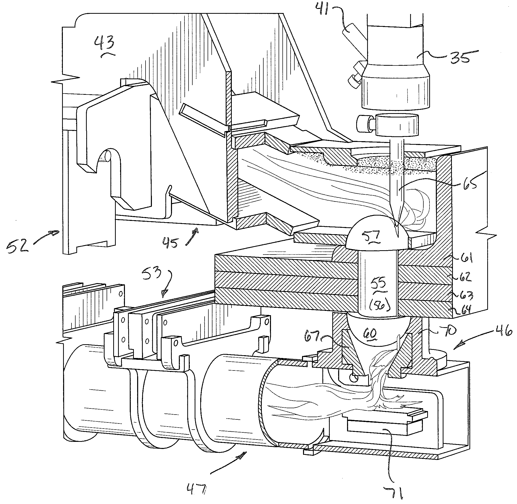
As noted elsewhere herein, the lack of a cylindrical opening for the rivet and the interaction of the rivet with the uneven plies makes rivet removal particularly difficult using conventional techniques.

Method used


Image

  • Method and apparatus for rivet removal and in-situ rehabilitation of large metal structures
  • Method and apparatus for rivet removal and in-situ rehabilitation of large metal structures
  • Method and apparatus for rivet removal and in-situ rehabilitation of large metal structures

Examples


Embodiment Construction

[0050]FIGS. 7 through 15 illustrate a number of aspects of the invention. In a first aspect, the invention is an apparatus for cutting structural components in-place without releasing displaced materials, including lead paint and other potentially hazardous materials. FIG. 7 illustrates such an apparatus in one aspect in which the structural component is illustrated as a first girder 30, a second girder 31, and a reinforcing ply 32. As illustrated in FIG. 7, a rivet 33 joins the first girder 30 to the ply 32. It will be understood, of course, that a number of other rivets typically join such pieces together, some of which are illustrated at 34 in FIG. 7.

[0051] The cutting apparatus includes a water jet cutting head 35 the nozzle of which is not visible in the view of FIG. 7. The water jet cutting head is positioned on a first face of the joined metal components 31, 30, and 32 for cutting into and through the components with the high-pressure water jet, which preferably carries an a...


PUM

PropertyMeasurementUnit
perimeteraaaaaaaaaa
perimeter shapeaaaaaaaaaa
pressureaaaaaaaaaa

Abstract

A method and apparatus are disclosed for replacing riveted metal components in place on existing metal structures. The method includes the steps of positioning a rivet removing tool at a rivet on an in situ structural component that is maintained in place by a plurality of rivets, encoding the position of the rivet removing tool at the rivet and transmitting the encoded position of the rivet to a processor, removing the rivet, sequentially moving the rivet removing tool to each of the rivets on the structural component that hold the structural component in place, sequentially encoding the position of the rivet removing tool at each rivet, transmitting the encoded the position of each rivet to the processor, and removing each rivet with the tool when the tool is at the rivet, designing a replacement component based upon the encoded positions of the rivets and fabricating the replacement component based on the transmitted rivet positions.

Description

BACKGROUND OF INVENTION [0001] The present intention relates to rehabilitation of metal structures and in particular relates to rivet replacement and component part replacement on metal bridges. [0002] Steel or iron bridges came into wide existence during the 19th century, and the use of rivets to fix structural components to one another covers a number of decades, extending from before 1900 to at least the late 1950's. Accordingly, based on normal use and fatigue on such structures, a large number will need to be either rehabilitated or replaced in the foreseeable future. Smaller structures are often easier and less expensive to replace instead of repair, but as the size of the structure increases, rehabilitation becomes a more attractive option, and in some circumstances an economic necessity. [0003] Such steel or iron structures are formed by a large number of individual girders (using the term as broadly as possible) as well as various connecting components such as splice plates...

Claims


Application Information

Patent Timeline
Patent Type & Authority Applications(United States)
IPC IPC(8): B21J15/10B21J15/28B21J15/50B23P6/00
CPCB21J15/10B21J15/28B21J15/50B23P6/00Y10T29/49822Y10T29/53Y10T29/49821Y10T29/49735Y10T29/4973Y10T29/49734Y10T29/49732
Inventor MOTZNO, DOUGLAS W.LOUGHTON, BRUCE J.
Owner HYDRILL INC
Why Eureka
Try Eureka