Contouring shave

a shave and contour technology, applied in the field of contouring shave, can solve the problems of affecting the smoothness of the finished contour, the inability of the tool the inability of the tool to work in the freeform surface to continuously blend the finished contour, etc., and achieves the effect of reducing the difficulty of shav

Inactive Publication Date: 2005-04-21
DENKER JAMES M
View PDF46 Cites 18 Cited by
  • Summary
  • Abstract
  • Description
  • Claims
  • Application Information

AI Technical Summary

Benefits of technology

[0015] The body member adjustably locates and holds fixedly a lateral guide member. This guide member can be held in the form of a 90° V in close proximity to the workpiece-engaging surface of the regulating post, and the blade has a primary flat bevel and a secondary flat bevel that defines a straight cutting edge. Alternately, the body member adjustably locates and holds fixedly a lateral guide member in the form of a 90° V in close proximity to the workpiece-engaging surface of the regulating post, and the blade has a primary flat bevel and a secondary flat bevel that defines a straight cutting edge that is centrally notched at the same secondary bevel angle with a quarter-circle arc of arbitrary radius.

Problems solved by technology

These tools are not as well suited to working areas of freeform surfaces to continuously blended finished contours, a task best performed by a tool that merely shaves or planes the surface, rather than cutting deeply into the wood under the skillful guidance, control, and physical effort of the woodcarver.
Obviously, planes having flat or concave soles have limited utility on free-form three-dimensional surfaces because they can engage and cut only convex surfaces whose radius of curvature is less than that of the sole or the cutting edge.
A plane taking a full-width chip in hardwood, or even most softwood, requires a lot of force to push (or pull).
However, when used to plane a flat surface, a block plane becomes much harder to push and control with just one hand, so the other hand is often needed to assist the gripping hand.
Aside from undesirably high force requirements, planes also have another characteristic that can cause great difficulty.
However, there are woods having a curly grain pattern, such as Bird's Eye Maple and Tiger Maple, that cannot be planed in any direction without going against the grain in some portion of any cutting stroke.
Whenever such an interruption occurs, it is likely to produce a tear-out in the surface.

Method used


Image

  • Contouring shave
  • Contouring shave
  • Contouring shave

Examples


second embodiment

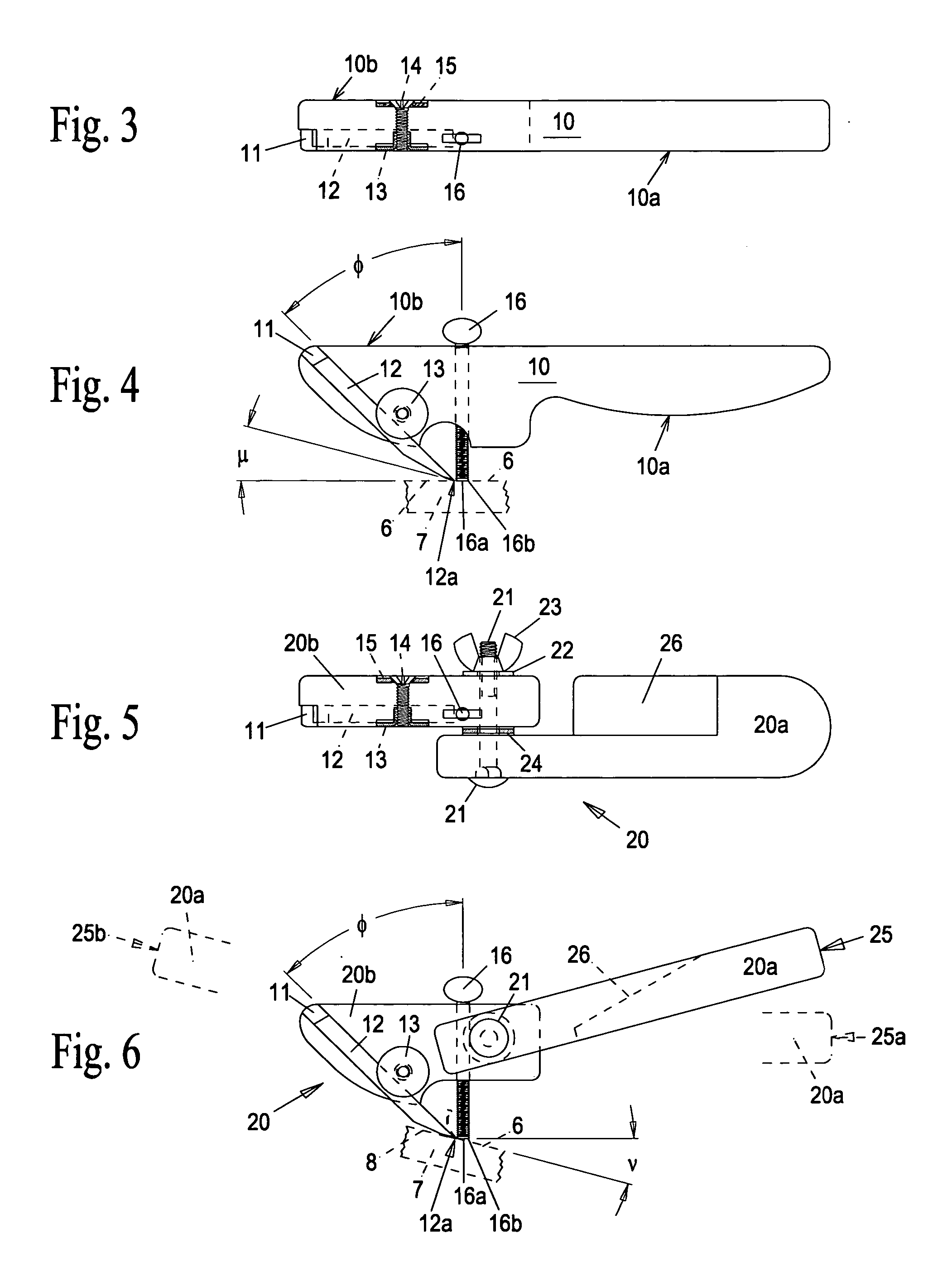
[0048] Referring now to FIG. 5 and FIG. 6, the invention is shown comprising a two-piece body or housing assembly 20 of hardwood, molded plastic, die-cast metal, or a combination of these or other materials, with the handle portion 20a and the main portion 20b joined to each other by a single carriage bolt 21, flat washer 22, and wing nut 23. Appropriate friction washers 24 between body portions 20a and 20b permit the handle portion 20a to be positioned and locked at any convenient angular position 25, between 25a (straight) and 25b (fully folded) with respect to the main portion 20b for cutting inside deep hollows or other confined spaces. The handle portion 20a is relieved in area 26 to permit counterclockwise rotation (folding) of the handle portion 20a to within 15° of horizontal. In this position 25b, the entire assembly 20 can be turned 180° around its vertical axis for one-handed use as a push plane where there is limited clearance for the handle 20a in the pull-cutting confi...

first embodiment

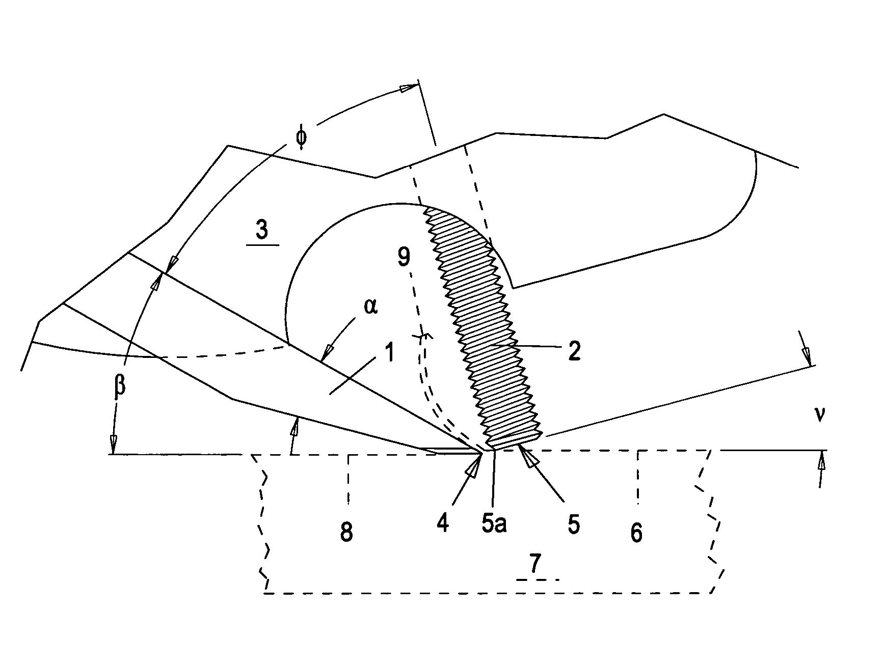
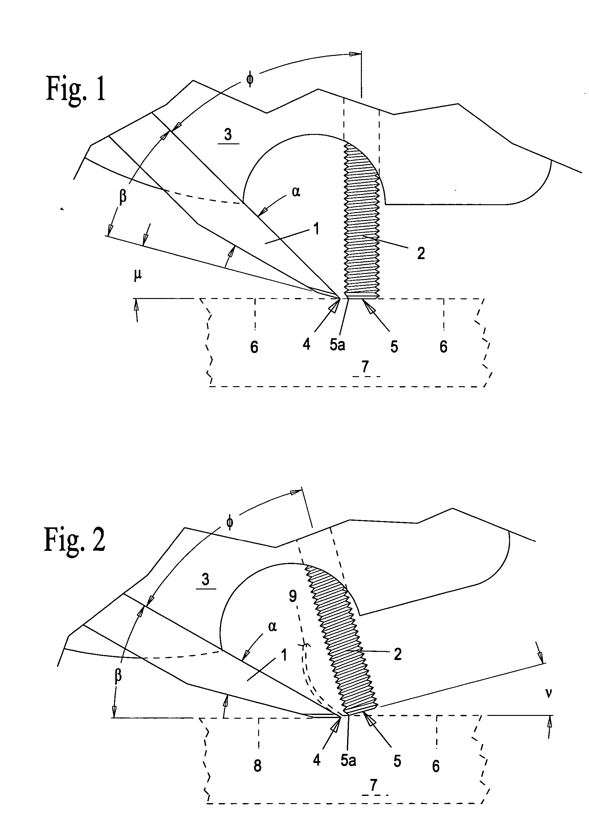
[0049] Again, for reference and to illustrate the fundamental relationship of the tool and workpiece during the cutting process, a partial workpiece 7 is shown in phantom in FIG. 6 tilted to an angle ν required for cutting edge 12a to cut into surface 6 and generate a new surface 8. With respect to the location of the thumbscrew 16 and the position and angle φ of the cutting blade 12, the geometry of the main portion 20b of this embodiment and the clamping means for blade 12 are the same for both the one-piece body and handle design 10 (FIG. 3 and FIG. 4) and the two-piece body and pivoting handle assembly 20 (FIG. 5 and FIG. 6). Both embodiments may be used interchangeably whenever there is no interference of the workpiece with the fixed handle portion 10a of the This ability is advantageous in prolonged work sessions, where the slightly different hand gripping positions serve to prevent the hand cramping that can occur when holding any single object tightly for a long period of t...

fourth embodiment

[0057]FIG. 13A shows the crowned cutting edge that is preferred for most applications of the embodiments of the invention, with the exception of the fourth embodiment described above, which is used only for chamfering 90° edges at 45° and requires a straight cutting edge to produce a flat chamfer. The curvature ρ of the cutting edge may be chosen as required by the application conditions, but in general, ρ must always be less than the minimum radius of concave curvature of the surface of a workpiece, to prevent the corners of the blade from leaving sharp grooves or dig-marks in the surface. A good rule of thumb is to choose ρ=twice the cutting width of the blade. For most work, ρ be in the range of 0.125 inches to 2.00 inches, with ρ=0.5 inches being typical for general use. A blade 0.25 inches width with ρ=0.125 is able to cut cleanly even when tilted 45° to either side, which is very useful in shaving the sides of cavities or grooves that are both narrow and deep. A very useful cr...


PUM


Abstract

The invention is directed to a hand tool for cutting shavings from the surface of a workpiece of wood (or other workable material) to shape and make smooth any three-dimensional surface having concave, flat, and/or convex contours. The thickness of the shavings is modulated by the angular relationship and distance between a blade and a regulating post. An embodiment comprises a combination body and handle holding a protruding cutting blade at an angle of about 30° to the surface of the workpiece, and an adjustable protruding post in front of the cutting edge to limit the effective exposure of the cutting edge as the tool is moved into contact with the workpiece. The embodiments provide a full view of the cutting zone and unrestricted one-hand use on surfaces of any contour.

Description

CROSS-REFERENCE TO RELATED APPLICATIONS [0001] This application claims the benefit of U.S. Provisional Patent Application Ser. No. 60 / 512,430 filed Oct. 20, 2003, the entire contents of which is incorporated herein by reference.TECHNICAL FIELD [0002] This invention relates generally to the field of woodworking tools. BACKGROUND [0003] In the hands of a skilled woodcarver, chisels and gouges are an excellent (and sometimes the only) hand tools that can cut virtually any contour on a workpiece. They are best used to cut specific shapes and details while working to layout lines, and for incising away sizeable chunks of waste material quickly. Often a mallet is used to drive the cutting edge into the wood. These tools are not as well suited to working areas of freeform surfaces to continuously blended finished contours, a task best performed by a tool that merely shaves or planes the surface, rather than cutting deeply into the wood under the skillful guidance, control, and physical eff...

Claims


Application Information

Patent Timeline
Patent Type & Authority Applications(United States)
IPC IPC(8): B27G17/02B27G17/04
CPCB27G17/04B27G17/025
Inventor DENKER, JAMES M.
Owner DENKER JAMES M
Why Eureka
Try Eureka