Energy-saving consumption-reducing short-range nitration dephosphorizing coupling technique with synchronous denitrification and device thereof

A technology for coupling nitrification and phosphorus removal and short-range nitrification, which is applied in the field of energy-saving and consumption-reducing short-range nitrification and synchronous denitrification and phosphorus removal coupled processes and devices, can solve the problems of low nitrite accumulation rate and limited phosphorus removal, and achieves denitrification and denitrification removal. The effect of high phosphorus rate, reduction of reactor volume, and elimination of internal circulation steps

Active Publication Date: 2010-08-04
TSINGHUA UNIV
View PDF5 Cites 20 Cited by
  • Summary
  • Abstract
  • Description
  • Claims
  • Application Information

AI Technical Summary

Problems solved by technology

[0004] In the Chinese invention patent "Short-range denitrification and simultaneous denitrification and phosphorus removal process and device" 200810222814.4, the improved A 2 / O process, that is, the anaerobic-aerobic-aerobic-anoxic-anoxic-anoxic process has carried out short-range nitrification and simultaneous denitrification phosphorus removal, but there are still the following deficiencies: the accumulation rate of nitrite is not high, and phosphorus removal is limited. Limitation, cannot effectively remove nitrogen and phosphorus

Method used


Image

  • Energy-saving consumption-reducing short-range nitration dephosphorizing coupling technique with synchronous denitrification and device thereof
  • Energy-saving consumption-reducing short-range nitration dephosphorizing coupling technique with synchronous denitrification and device thereof

Examples


Embodiment Construction

[0018] The present invention will be further described below in conjunction with accompanying drawing:

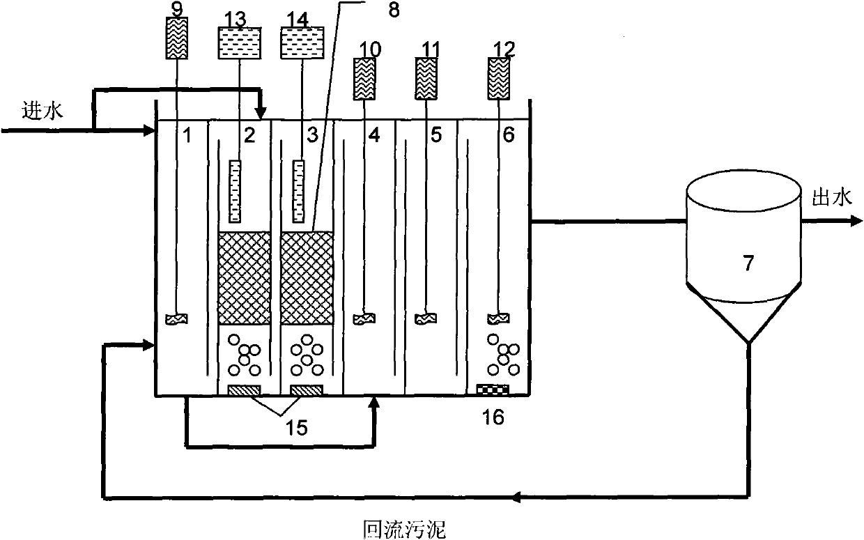
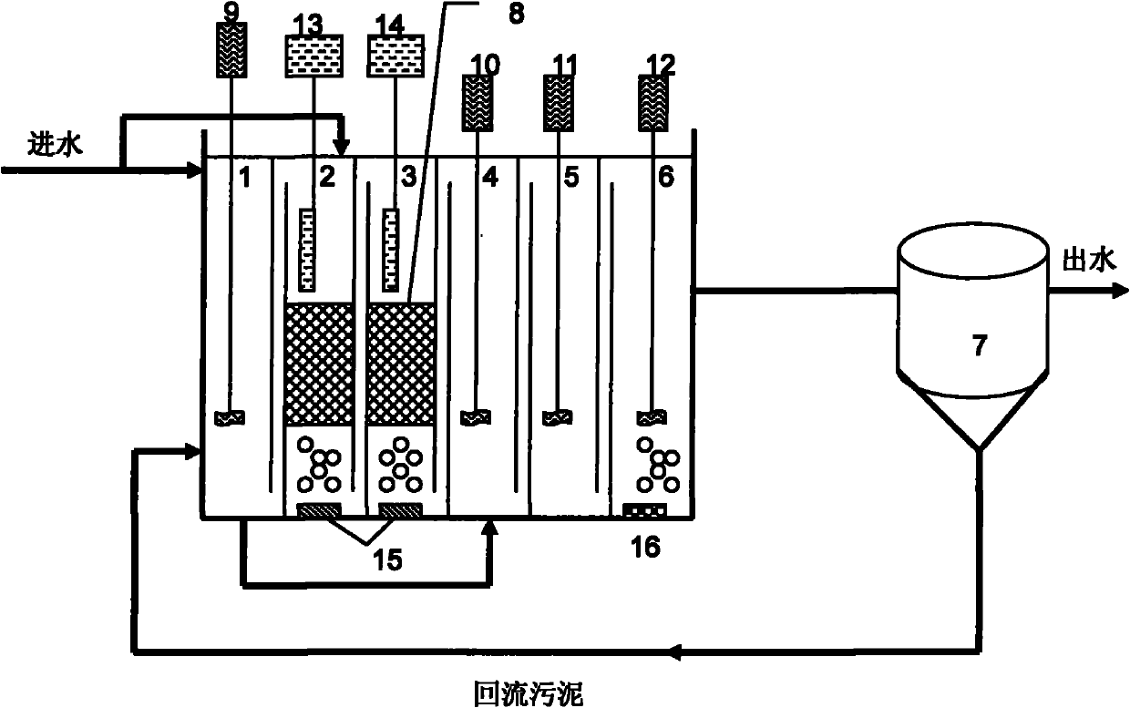
[0019] A coupling device for energy-saving and consumption-reducing short-cut nitrification and simultaneous denitrification and phosphorus removal. The schematic diagram of the device is as follows: figure 1 As shown, the device is mainly composed of a water inlet pipe, an integrated reactor, and a sedimentation tank 7. The internal anaerobic reactor 1 of the integrated reactor, the first aerobic reactor 2, the second aerobic reactor 3, the first deficient Oxygen reactor 4, the second anoxic reactor 5, fast aerobic reactor 6 are connected in sequence, in anaerobic reactor 1, the first anoxic reactor 4, the second anoxic reactor 5, fast aerobic reaction Agitators 9, 10, 11, 12 are respectively arranged in the container 6, dissolved oxygen DO automatic controllers 13, 14 are respectively arranged in the first aerobic reactor 2 and the second aerobic reactor 3, and the first ...


PUM


Abstract

The invention discloses an energy-saving consumption-reducing short-range nitration dephosphorizing coupling technique with synchronous denitrification and a device thereof, belonging to technical field of domestic and industrial sewage treatment. A metal carrier bed is installed in an aerobic section with integrated reaction, and is made of iron wood shaving washed through acid cleaning; and the outer part of the iron wood shaving is covered by wire netting. Under conditions of normal temperature and low dissolved oxygen, the aims of short-range nitration and synchronous denitrification can be realized; an anaerobic section is used for finishing phosphorous releasing; the aerobic section is used for finishing short-range nitration, an anoxic section is used for finishing denitrification for removing phosphorous, a fast aerobic section is used for removing remaining ammonia and nitrogen and phosphorous. The invention uses iron wood shaving with low cost to realize stable accumulation of nitrite; the aerating amount is small, the carbon source is saved, and denitrification for phosphorous removing is carried out by taking the nitrite produced via short-range nitration as electron donor, thus the nitrogen and phosphorous can be removed synchronously; and the problem that the nitrite in water could damage the environment and has toxicity is solved. The invention can realize the aims of saving energy and reducing consumption to the largest extent, and is suitable for purifying and treating domestic sewage continuously for a long time.

Description

technical field [0001] The invention belongs to the technical field of domestic and industrial sewage treatment, and in particular relates to an energy-saving and consumption-reducing short-range nitrification synchronous denitrification phosphorus removal coupling process and device. Background technique [0002] Anaerobic-Anoxic-Aerobic (A 2 / O) process is widely used in urban sewage treatment because of its good nitrogen and phosphorus removal effect. However, high operating costs and high energy consumption are still a problem faced by urban sewage treatment plants. Therefore, research on new energy-saving and consumption-reducing A 2 / O process is of great significance for reducing the operating cost of sewage treatment plants. The basic principle of short-cut nitrification and denitrification biological nitrogen removal is to control the nitrification process in the nitrite stage and prevent NO 2 - further nitrification and then direct denitrification. The advant...

Claims


Application Information

Patent Timeline
Patent Type & Authority Applications(China)
IPC IPC(8): C02F9/14C02F101/16
Inventor 黄霞吴春英支霞辉
Owner TSINGHUA UNIV
Why Eureka
Try Eureka